Table of Contents
Advertisement
Quick Links
Advertisement
Table of Contents

Related Manuals for EnerSys Outback Power EnergyCell 1000XLC


Summary of Contents for EnerSys Outback Power EnergyCell 1000XLC
- Page 1 EnergyCell 1000XLC Owner’s Manual...
- Page 2 EnergyCell 1000XLC Series Battery Owner’s Manual © 2019 by OutBack Power. All Rights Reserved. Trademarks OutBack Power and the OutBack Power logo are trademarks owned and used by OutBack Power, an EnerSys company. These trademarks may be registered in the United States and other countries. Date and Revision November 2019, Revision A...
-
Page 3: Table Of Contents
Table of Contents Important Safety Instructions ............... 4 Additional Resources ........................4 Introduction ..................5 Audience ............................5 EnergyCell 1000XLC ........................5 Materials Required .......................... 7 Tools (use insulated tools only) ........................7 Accessories ..............................7 Storage and Environment Requirements ..................7 Temperatures ...............................7 ... -
Page 4: Important Safety Instructions
Safety Instructions Important Safety Instructions READ AND SAVE THESE INSTRUCTIONS! This manual contains important safety instructions for the EnergyCell battery. These instructions are in addition to the safety instructions published for use with all OutBack products. Read all instructions and cautionary markings on the EnergyCell battery and on any accessories or additional equipment included in the installation. -
Page 5: Introduction
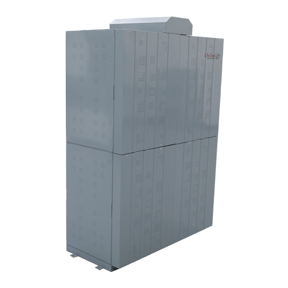
Introduction Audience This manual is intended for use by anyone required to install and operate this battery. Be sure to review this manual carefully to identify any potential safety risks before proceeding. The owner must be familiar with all the features and functions of this battery before proceeding. Failure to install or use this battery as instructed in this manual can result in damage to the battery that may not be covered under the limited warranty. - Page 6 Introduction " " (112.5 cm) (55.5 cm) " (171 cm) Terminal Figure 2 EnergyCell 1000XLC Assembly IMPORTANT: The surface supporting the assembled cabinet must be designed to support 27.3 psi (1.92 kg/cm ). Concrete is ideal. Total weight of cabinet assembly with batteries is 4,574 lb (2,075 kg).
-
Page 7: Materials Required
Introduction Materials Required Tools (use insulated tools only) Digital voltmeter Drill Hammer Level Socket wrench Torque wrench calibrated in inch-pounds Box end wrench Battery lifting equipment (eyebolts and straps) and fork lift to lift battery modules Rubber gloves Full face shield Plastic apron Portable eyewash Spill kit... -
Page 8: Self-Discharge
Introduction Self-Discharge Unlike many conventional batteries, 1000XLC batteries won’t discharge significantly over time once charged, even in storage. This is especially true if the batteries are kept relatively cool. Fully charged, the natural (“rest”) voltage of 1000XLC batteries is approximately 52.0 Vdc (2.2 volts per cell or Vpc). - Page 9 Introduction The more accurate method is to use a battery monitor such as the OutBack FLEXnet DC. Using a sensor known as a shunt, the monitor observes the current through the battery. It keeps a total of amp-hours lost or gained by the battery and can give accurate SoC readings. The EnergyCell can be discharged and recharged (cycled) regularly to a level as low as 50% depth of discharge (DoD).
- Page 10 Introduction This page intentionally left blank. 900-0258-01-00 Rev A...
-
Page 11: Installation
Installation System Installation Considerations CAUTION: Fire Hazard Failure to ventilate the battery compartment can result in the buildup of hydrogen gas, which is explosive. The battery enclosure or room must be well-ventilated. This ventilation protects against accidental gas buildup. All EnergyCell batteries are valve-regulated and do not normally emit noticeable amounts of gas. -
Page 12: Pre-Installation Check
Installation Four Module Stack Single Module Figure 5 Single Module and Four Module Stack Pre-Installation Check Inspect batteries carefully for any physical damage or leaking and check safety vents. Ensure all batteries in each module are oriented consistently with positive terminals on one side of each battery and negative terminals on the other side. -
Page 13: Installation Procedure
Installation Installation Procedure 1. Install 4 support bars on module frame and fasten with M5 screws (3 screws per bar). The set of 2 bars closest to the positive battery terminals should be installed adjacent to each other, while the bars closest to the negative terminals should be installed with their outer ends flush with the outer edge of the module frame and a gap in the module center between the two bars. - Page 14 Installation 2. After installing support bars on each of the 4 modules, number each module #1 to #4. Module #1 will be the bottom module in the stack. 3. Install 3 mounting beams on module #1 (the bottom module) using M12 bolts and M3 screws—note that beams fasten onto the same side of the module frame as the gapped support bars installed previously, which is also the side closest to the negative terminals.
- Page 15 Installation 4. Anchor module #1, which will be the bottom module of the assembled cabinet, onto a strong and level mounting surface (concrete floor is ideal). Keep at least a 2" (5 cm) gap between the module and any wall to allow air circulation. Follow these steps to anchor the module: a.
- Page 16 Installation 5. Carefully position module #2 on top of module #1 and secure with M12 bolts. If possible, use a forklift or powered lifting device to lift the module (1,100 lb/500 kg) after attaching a heavy-duty strap to each side of the module using eyebolts (if no powered lift device is available, remove the batteries from the module one by one [200 lb/90 kg], stack the empty module and then insert the batteries).
- Page 17 Installation 6. Before installing the top module #4, install 2 red insulators with M3 screws near the center of the top front of module #4 frame, in the gap between the two support bars installed earlier. Install cover on top of module #4. Then install #4 module on top of module #3.
- Page 18 Installation 7. Check again to be sure batteries are correctly positioned with orientation alternating between rows. If correct, the support bars attached to front of modules should be matched, with the center gap between support bars showing where module #2 meets module #3, and the support bars adjacent to each other (no gap) where modules #1 and #2 meet as well as where modules #3 and #4 meet.
- Page 19 Installation 8. Lightly brush the terminal contact surface areas with a brass bristle brush or the equivalent, then coat with dielectric grease such as NO-OX-ID or NCP-2. Carefully install short bus bars using M10 bolts so that batteries are connected in series. Torque bolts to 28.1 to 33.8 N⋅m (287 to 344 kgf...
- Page 20 Installation 9. There are 4 different types of long bus bars (A, B, C, and D). Connect these as shown below. Bus bars A and B are secured with M10 bolts, while bus bars C and D are secured with M8 bolts. Torque M10 bolts to 17.2 ± 2.5 N⋅m (175±...
- Page 21 Installation 10. Install side shields using M3 screws. Begin at the back, then proceed to the front, and lastly both sides. M3 Screws (16 per side) Figure 14 Install Long Side Panels 900-0258-01-00 Rev A...
- Page 22 Installation 11. Install front cover (4 separate panels). Screws Screws Screws Figure 15 Install Front Cover Panels 900-0258-01-00 Rev A...
- Page 23 Installation 12. Install battery cables to the top bus bars using M12 bolts. Install the Equipment Grounding Conductor to the screw provided near the lower rear corner of the side panel. Battery Cables M12 Bolt Equipment Grounding Conductor Figure 16 Install Battery Cables 900-0258-01-00 Rev A...
- Page 24 Installation 13. Install the bus bar cover on top by locking into place with side tabs and securing with two M3 screws on back side of cover. Cover M3 Screws (back) Retainer Tab Figure 17 Install Bus Bar Terminal Cover 900-0258-01-00 Rev A...
-
Page 25: Operation
Operation Commissioning After installing the battery bank, measure the overall open circuit voltage of the bank as well as each individual cell, and record these values. If the system voltage is less than 50.6 Vdc (or individual cell voltage less than 2.11 Vpc), apply a freshening charge to the bank as follows: To apply a freshening charge: Perform a bulk charge with a recommended charge current of 168 Adc but not to exceed the maximum limit of 200 Adc to 58 Vdc (2.42 Vpc). -
Page 26: Float Stage
Operation Float Stage The float stage maintains the battery at a full state of charge. Set float between 53 and 54Vdc (2.21 to 2.25 Vpc) for 2 hours . Equalization Once every 14 days the batteries should be given an equalization charge to maintain optimal battery health and to compensate the 1-6% loss during daily cycling. -
Page 27: Remote Temperature Sensor
Operation EnergyCell 1000XLC Required Compensation The factor is 5 mV per cell (0.030 Vdc or 30 mV per battery) per degree C above or below room temperature (77°F or 25°C) when the battery is regularly cycled. Remote Temperature Sensor OutBack inverter/chargers and charge controllers are equipped with the Remote Temperature Sensor (RTS) which attaches to the battery and automatically adjusts the charger settings. - Page 28 Operation NOTES: 900-0258-01-00 Rev A...
-
Page 29: Troubleshooting And Maintenance
Troubleshooting and Maintenance Table 1 Troubleshooting Category Symptom Possible Cause Remedy Normal life cycle Replace battery bank when (or before) capacity drops to unacceptable levels. Reduced operating time Defective cells Test and replace battery as necessary. Excessively cold battery Carefully warm up the battery. Undersized cabling Increase cable ampacity to match loads. -
Page 30: Periodic Evaluation
Troubleshooting and Maintenance Periodic Evaluation Upon replacement of a battery, all interconnect hardware should be replaced at the same time. To keep track of performance and identify batteries that may be approaching the end of their life, perform the following tests during on a quarterly basis following commissioning (see page 25). -
Page 31: Cell Voltage Records
Troubleshooting and Maintenance Cell Voltage Records Date: Date: Date: Cell 1 Cell 2 Cell 3 Cell 4 Cell 5 Cell 6 Cell 7 Cell 8 Cell 9 Cell 10 Cell 11 Cell 12 Cell 13 Cell 14 Cell 15 Cell 16 Cell 17 Cell 18 Cell 19... - Page 32 Troubleshooting and Maintenance NOTES: 900-0258-01-00 Rev A...
-
Page 33: Specifications
Specifications Table 2 Specifications EnergyCell 1000XLC Cells Per Unit Voltage Per Unit 77°F Optimal Operating Temperature (25°C) –40°F to 122°F Maximum Operating Range (–40°C to 50°C) Operating Temperature Range –4°F to 104°F (Storage) (–20° to 40° C) Operating Temperature Range –4°... - Page 34 Specifications Table 4 Weight and Volume of Battery Components Battery Electrolyte Electrolyte H2SO4 Lead Weight Weight Volume Weight Weight Battery Type: (kg) (lb) (kg) (lb) (ml) (gal) (kg) (lb) (kg) (lb) EnergyCell 1000XLC 73.8 162.73 16.89 37.24 13,799 3.65 5.14 11.33 53.02 116.90 900-0258-01-00 Rev A...
- Page 35 EnergyCell Batteries This page intentionally left blank. 900-0258-01-00 Rev A...
- Page 36 Masters of the Off-Grid.™ First Choice for the New Grid. 17825 – 59 Avenue N.E. Suite B Arlington, WA 98223 USA...
Need help?
Do you have a question about the Outback Power EnergyCell 1000XLC and is the answer not in the manual?
Questions and answers