Pioneer MVH-350BT Service Manual

Pioneer MVH-350BT Service Manual

Rds media center receiver
Hide thumbs Also See for MVH-350BT:

Advertisement

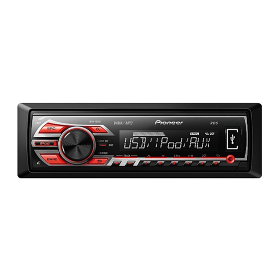
RDS MEDIA CENTER RECEIVER
MVH-350BT
MVH-355BT
MVH-150UI
MVH-155UI
MVH-155UI
MVH-159UI
PIONEER CORPORATION
PIONEER ELECTRONICS (USA) INC. P.O. Box 1760, Long Beach, CA 90801-1760, U.S.A.
PIONEER EUROPE NV Haven 1087, Keetberglaan 1, 9120 Melsele, Belgium
PIONEER ELECTRONICS ASIACENTRE PTE. LTD. 253 Alexandra Road, #04-01, Singapore 159936
PIONEER CORPORATION 2012
/XMEW5
/XMES
/XMES1
/XMID
1-1, Shin-ogura, Saiwai-ku, Kawasaki-shi, Kanagawa 212-0031, Japan
MVH-350BT/XMEW5
/XMES
ORDER NO.
CRT5065
/XMEW5
K-ZZZ AUG. 2012 Printed in Japan

Advertisement

Table of Contents
loading

Summary of Contents for Pioneer MVH-350BT

  • Page 1 PIONEER CORPORATION 1-1, Shin-ogura, Saiwai-ku, Kawasaki-shi, Kanagawa 212-0031, Japan PIONEER ELECTRONICS (USA) INC. P.O. Box 1760, Long Beach, CA 90801-1760, U.S.A. PIONEER EUROPE NV Haven 1087, Keetberglaan 1, 9120 Melsele, Belgium PIONEER ELECTRONICS ASIACENTRE PTE. LTD. 253 Alexandra Road, #04-01, Singapore 159936 PIONEER CORPORATION 2012 K-ZZZ AUG.
  • Page 2: Safety Information

    CAUTION Danger of explosion if battery is incorrectly replaced. Replaced only with the same or equivalent type recommended by the manufacturer. Discord used batteries according to the manufacturer's instructions. MVH-350BT/XMEW5...
  • Page 3: Table Of Contents

    9.2 EXTERIOR ...............................26 10. SCHEMATIC DIAGRAM..........................28 10.1 TUNER AMP UNIT (GUIDE PAGE)......................28 10.2 KEYBOARD UNIT ..........................34 10.3 BT UNIT..............................36 11. PCB CONNECTION DIAGRAM ........................38 11.1 TUNER AMP UNIT ..........................38 11.2 KEYBOARD UNIT...........................42 11.3 BT UNIT ..............................43 12. ELECTRICAL PARTS LIST...........................44 MVH-350BT/XMEW5...
  • Page 4: Service Precautions

    2. Before disassembling the unit, be sure to turn off the power. Unplugging and plugging the connectors during power-on mode may damage the ICs inside the unit. 3. Be careful in handling ICs. Some ICs such as MOS type are so fragile that they can be damaged by electrostatic induction. MVH-350BT/XMEW5...
  • Page 5: Notes On Soldering

    Compared with eutectic solders, lead-free solders have higher bond strengths but slower wetting times and higher melting temperatures (hard to melt/easy to harden). The following lead-free solders are available as service parts: Parts numbers of lead-free solder: GYP1006 1.0 in dia. GYP1007 0.6 in dia. GYP1008 0.3 in dia. MVH-350BT/XMEW5...
  • Page 6: Specifications

    2. SPECIFICATIONS 2.1 SPECIFICATIONS MVH-350BT/XMEW5, MVH-150UI/XMEW5 General Power source......14.4 V DC (10.8 V to 15.1 V allowable) USB standard specification Grounding system ....Negative type ........USB 2.0 full speed Maximum current consumption Maximum current supply ........10.0 A ........1A Backup current ....4.0 mA or less USB Class ......MSC (Mass Storage Class)
  • Page 7 Equalizer (5-Band Graphic Equalizer): Frequency....80 Hz/250 Hz/800 Hz/ 2.5 kHz/8 kHz Equalization range ..±12 dB (2 dB step) Subwoofer (mono): Frequency....50 Hz/63 Hz/80 Hz/100 Hz/ 125 Hz/160 Hz/200 Hz Slope......–6 dB/oct, –12 dB/oct Gain ......+6 dB to –24 dB Phase......Normal/Reverse MVH-350BT/XMEW5...
  • Page 8: Disc/Content Format

    2.2 DISC/CONTENT FORMAT The Bluetooth word mark and logos are owned by the Bluetooth SIG, Inc. and any use of such marks by Pioneer Corporation is under license. Other trademarks and trade names are those of their respective owners. MVH-350BT/XMEW5...
  • Page 9: Basic Items For Service

    Distortion Noise Volume too low Volume too high Volume fluctuating Sound interrupted 3.2 PCB LOCATIONS BT Unit Tuner Amp Unit 350BT/XMEW5 355BT/XMES Keyboard Unit A:MVH-350BT/XMEW5 B:MVH-355BT/XMES C:MVH-150UI/XMEW5 D:MVH-155UI/XMES E:MVH-155UI/XMES1 F:MVH-159UI/XMID Unit Number QWM3482(A) Unit Number QWM3483(B) Unit Number QWM3477(C) Unit Number...
  • Page 10: Block Diagram

    4. BLOCK DIAGRAM TUNER AMP UNIT JA401 ANTENNA FMMIXIN1 DACOUTL PINDIN LNAIN RF FRONT END IC IC401 TDA7706 :MVH-350BT/XMEW5 I2CSCL TUN_SCL :MVH-355BT/XMES I2CSDA TUN_SDA :MVH-150UI/XMEW5 RSTN TUNRES :MVH-155UI/XMES :MVH-155UI/XMES1 :MVH-159UI/XMID JA891 KEYAD KEYAD WIRED KEYD KEYD REMOTE SYSTEM MICRO COMPUTER...
  • Page 11 BSENS SYSPW DSENS DSENS DSENS V1801 BTPW REMOTE CONTROL SENSOR IC1941 GP1UXC14RK ILM+B ILM+B D1952,D1953, D1967,D1968, D1954,D1956, D1969,D1971, SYNC D1957,D1958, D1972,D1973, D1951 D1981 D1959,D1960, D1974,D1975, DDON D1961,D1962, D1976,D1977, D1963,D1964, D1978,D1979, D1965,D1966 D1980 Q1953 USBCTL CN1911 USBFLG USB5V USB5V USB5V MVH-350BT/XMEW5...
  • Page 12: Diagnosis

    In case of the above signal, the communication Source keys with Grille microcomputer may fail. operative If the time interval is not 300 msec, the oscillator may be defective. Source ON SYSPW <- H Pin 8 Completes power-on operation. (After that, proceed to each source operation) MVH-350BT/XMEW5...
  • Page 13: Error Code List

    There are no Select a list that current. OFF, then to ACC songs in the contains songs. or ON and then current list. connect only NOT FOUND No related Transfer songs to compliant USB songs. the iPod. storage devices. MVH-350BT/XMEW5...
  • Page 14 Turn the ignition for the switch OFF and Bluetooth module then to ACC or of this unit. If the error message is still displayed after performing the above action, please contact your dealer or an authorized Pioneer Service Station. MVH-350BT/XMEW5...
  • Page 15: Connector Function Description

    5.3 CONNECTOR FUNCTION DESCRIPTION MICROPHONE INPUT MVH-350BT/XMEW5 WIRED FRONT ANTENNA REMOTE OUTPUT 15 13 11 9 7 5 3 1 CONTROL 16 14 12 10 8 6 4 2 REAR OUTPUT or SUBWOOFER OUTPUT 9 NC 1 FL+ 2 FR+...
  • Page 16 16 14 12 10 8 6 4 2 REAR OUTPUT or SUBWOOFER OUTPUT 9 NC 1 FL+ 10 NC 2 FR+ 3 FL- 11 NC 4 FR- 12 NC 5 RL+ 13 ACC 14 B.REM 6 RR+ 15 B.UP 7 RL- 8 RR- 16 GND MVH-350BT/XMEW5...
  • Page 17: Service Mode

    6. SERVICE MODE 6.1 DISPLAY TEST MODE 1 [How to enter Test mode] Press and hold BUTTON A and "LIST" buttons together, and turn BUP and ACC on. SOURCE LIST BUTTON A PHONE MVH-350BT/XMEW5 PHONE MVH-355BT/XMES iPod MVH-150UI/XMEW5 iPod MVH-155UI/XMES iPod...
  • Page 18: Display Test Mode 2

    The screen gets still when entering this item. On (an initial value or On (state when setting value of default entering test mode) Switching to next display menu) by pressing “ 1 ” + “ 3 ” buttons together. MVH-350BT/XMEW5...
  • Page 19: Software Version Up Method

    The display is continued until the power supply is turned OFF. If the power supply is turned ON again, the display is not changed. The upgrading using USB is disabled, so it is necessary to write programs in serial Flash using E10A. MVH-350BT/XMEW5...
  • Page 20: Disassembly

    - Removing the Tuner Amp Unit and the BT Unit (Fig.3) Tuner Amp Unit Disconnect the connector. Remove the two screws. Remove the two screws and then remove the Tuner Amp Unit. Remove the screw and then remove the BT Unit. BT Unit Fig.3 MVH-350BT/XMEW5...
  • Page 21 1. Attach the button from the front side of the panel. Fig.6 2. Attach the spring to the arm as shown in the figure. The bended tip of the spring is set to this side. Hitch the spring to the groove. Fig.7 MVH-350BT/XMEW5...
  • Page 22: Each Setting And Adjustment

    The frequency of the clock signal is 600 kHz that is divided by 20th of the oscillation frequency of X601 (12MHz). The clock signal should be 600 kHz(- 25 Hz, + 25 Hz). If the clock signal is out of the range, the X'tal (X601) should be replaced with new one. MVH-350BT/XMEW5...
  • Page 23 MVH-350BT/XMEW5...
  • Page 24: Exploded Views And Parts List

    For the applying amount of lubricants or glue, follow the instructions in this manual. (In the case of no amount instructions,apply as you think it appropriate.) 9.1 EXTERIOR 350BT/XMEW5 150UI/XMEW5 350BT/XMEW5 150UI/XMEW5 355BT/XMES 155UI/XMES 155UI/XMES1 159UI/XMID 355BT/XMES 155UI/XMES 155UI/XMES1 355BT/XMES 159UI/XMID 155UI/XMES 155UI/XMES1 159UI/XMID 350BT/XMEW5 355BT/XMES 159UI/XMID MVH-350BT/XMEW5...
  • Page 25 14-3 Service Network See Contrast table (2) Contain Box See Contrast table (2) Handle QNC3021 (2) CONTRAST TABLE MVH-350BT/XMEW5, MVH-355BT/XMES, MVH-150UI/XMEW5, MVH-155UI/XMES, MVH-155UI/XMES1 and MVH-159UI/XMID are constructed the same except for the following: Mark Description MVH-350BT/XMEW5 MVH-355BT/XMES MVH-150UI/XMEW5 MVH-155UI/XMES Microphone Assy CPM1083...
  • Page 26: Exterior

    9.2 EXTERIOR 355BT/XMES 155UI/XMES 155UI/XMES1 159UI/XMID 350BT/XMEW5 355BT/XMES 355BT/XMES 155UI/XMES 155UI/XMES1 159UI/XMID 350BT/XMEW5 355BT/XMES 350BT/XMEW5 355BT/XMES 350BT/XMEW5 150UI/XMEW5 MVH-350BT/XMEW5...
  • Page 27 See Contrast table (2) Screw BPZ20P100FTC Holder QNC3020 Panel QNS3387 Spring CBH2210 (2) CONTRAST TABLE MVH-350BT/XMEW5, MVH-355BT/XMES, MVH-150UI/XMEW5, MVH-155UI/XMES, MVH-155UI/XMES1 and MVH-159UI/XMID are constructed the same except for the following: Mark Description MVH-350BT/XMEW5 MVH-355BT/XMES MVH-150UI/XMEW5 MVH-155UI/XMES Cord Assy QDP3014 CDP1480 QDP3014 CDP1480...
  • Page 28: Schematic Diagram

    R801 2.2k R805 AUXL R803 SOURCE R806 R807 R804 AUXR NOTE : AUXGND MVH-350BT/XMEW5 Symbol indicates a resistor. MVH-355BT/XMES RGBST/ILMCLR2 No differentiation is made between chip resistors and MVH-150UI/XMEW5 CTF171 discrete resistors. RGBCK/ILMCLR1 US5V USB5V Symbol indicates a capacitor. MVH-155UI/XMES...
  • Page 29 R812 RGBCK/ILMCLR1 R961 R813 RGBDT/DIMMER 2.2k DIAG MASK C330 Dim off 12.13 V R814 2.2k Q875 KYDT Dim on 8.03 V TPD1052F DPDT LTC043EEB R816 2.2k ROT0 ILMPW B.REM&A.ANT R817 2.2k ROT1 SWVDD L851 IC801 DPDT OUTY TC7SET08FUS1 SWVDD MVH-350BT/XMEW5...
  • Page 30 PREOUT MVH-350BT/XMEW5...
  • Page 31 POWER SUPPLY MVH-350BT/XMEW5...
  • Page 32 MVH-350BT/XMEW5...
  • Page 33 MVH-350BT/XMEW5...
  • Page 34: Keyboard Unit

    KDT1 S1842 SEG51 KDT0 SOURCE DGND IC1941 GP1UXC14RK REMOTE 5 MHz X1801 CSS1547-A R1942 R1944 L1801 DGND DGND ILLUMINATION only A, C DGND except A, C V1801 CAW2024 SEGMENT LCD LTC014 COLOR2 BLUE only B ILMGND D1952-D1966 : FC-F1608BK-470H5 MVH-350BT/XMEW5...
  • Page 35 AUX:+2.2 dBs DSENS ILLUMINATION DGND CN1911 CKS6443-A C1911 0.1u/16 LTC014EEB LTC014EEB Q1952 Q1953 ILMGND DGND COLOR1 USB:±0.0 dBs only A USBGND except B D1967-D1981 : FC-1608SXK630D08 Q1951 MVH-350BT/XMEW5 only B MVH-355BT/XMES MVH-150UI/XMEW5 MVH-155UI/XMES ILMCLR MVH-155UI/XMES1 MVH-159UI/XMID ILMGND except B MVH-350BT/XMEW5...
  • Page 36: Bt Unit

    10.3 BT UNIT 1u/10 MIC_BIAS MIC1P BT18ON MIC1N BT1.8V BOOTS 3.3V BT1.8V RESET BT1.8V BT3.3V BT3.3V DBG_Tx IC21 DBG_Rx VOUT VSS1 VSS2 ON/OFF S-1172B18-E6 CN21 CKS6346-A BT MODULE MVH-350BT/XMEW5...
  • Page 37 BT UNIT (only A, B) MVH-350BT/XMEW5 MVH-355BT/XMES MVH-150UI/XMEW5 MVH-155UI/XMES MVH-155UI/XMES1 MVH-159UI/XMID CN23 CKS3857-A BTDATA BTSCK BTRLCK CN971 NRST_CPU 3.3V SYSTOBT BTTOSYS BT3.3V IC22 S-1206B33-U3 MIC1P MIC1N MVH-350BT/XMEW5...
  • Page 38: Pcb Connection Diagram

    R304 C252 C312 Chip Part P.C.Board R307 R302 R555 D551 C562 R311 C551 C556 C557 C563 C558 C555 C564 IC551 C553 R553 R552 R554 C552 C565 L551 D552 CN23 (only A, B) MVH-350BT/XMEW5 MVH-355BT/XMES MVH-150UI/XMEW5 MVH-155UI/XMES MVH-155UI/XMES1 MVH-159UI/XMID FRONT MVH-350BT/XMEW5...
  • Page 39 CN701 R703 R877 C872 C852 IC552 R878 C561 C873 C802 L851 C851 C560 R801 C811 C559 R808 R851 L801 C805 C808 C803 C809 IC801 R804 R803 D802 D811 D803 R813 VA802 C804 C810 R818 CN801 CN1931 C806 C801 FRONT MVH-350BT/XMEW5...
  • Page 40 TUNER AMP UNIT TESTIN MVH-350BT/XMEW5...
  • Page 41 SIDE B MVH-350BT/XMEW5...
  • Page 42: Keyboard Unit

    D1978 D1964 D1977 D1963 CN801 D1976 D1962 D1975 D1961 D1973 D1957 R1802 D1974 D1956 R1987 R1988 D1968 D1960 R1989 D1953 D1972 R1973 C1953 R1981 R1975 R1986 R1984 R1932 R1931 R1956 C1951 D1952 C1958 R1953 D1959 D1967 D1971 R1993 D1955 MVH-350BT/XMEW5...
  • Page 43: Bt Unit

    11.3 BT UNIT BT UNIT SIDE A (only A, B) CN971 BT MODULE BT UNIT SIDE B (only A, B) MVH-350BT/XMEW5 MVH-355BT/XMES MVH-150UI/XMEW5 MVH-155UI/XMES MVH-155UI/XMES1 MVH-159UI/XMID MVH-350BT/XMEW5...
  • Page 44: Electrical Parts List

    The expression of the unit in this manual is shown by u instead of µ. Please do not make a mistake. Circuit Symbol and No. Part No. Circuit Symbol and No. Part No. A:MVH-350BT/XMEW5 IC 551 (A,19,111) IC BD9876EFJ B:MVH-355BT/XMES...
  • Page 45 R 637 (A,100,90) RS1/16SS473J R 312 (A,99,129) RS1/16SS103J R 401 (A,161,106) RS1/16SS221J R 638 (A,104,92) RS1/16SS473J R 402 (A,161,100) RS1/16SS751J R 639 (A,97,91) RS1/16SS472J R 403 (A,139,104) (A,C,D,E,F) RS1/16SS391J R 640 (A,98,91) RS1/16SS472J (A,139,104) (B) RS1/16SS331J R 643 (A,99,82) RS1/16SS104J MVH-350BT/XMEW5...
  • Page 46 CKSRYB105K16 R 953 (A,125,115) (C) RS1/16SS153J C 402 (A,155,101) CKSSYB103K16 C 403 (A,152,102) CKSRYB105K10 R 961 (A,127,112) RS1/16SS103J R 962 (A,130,113) RS1/16SS103J C 405 (A,162,101) CKSSYB103K16 R 963 (A,129,112) RS1/16SS105J C 406 (A,160,101) CKSSYB103K16 R 973 (A,90,63) (A,B) RS1/16SS0R0J MVH-350BT/XMEW5...
  • Page 47 (A,32,114) 4.7 uF CCG1201 C 966 (A,128,112) CKSSYB333K16 C 565 (A,15,107) 4.7 uF CCG1222 C 969 (A,135,113) 22 uF DCH1256 C 601 (A,104,66) CKSSYB104K10 C 973 (A,98,53) (A,B) CCSSCH470J50 C 602 (A,109,65) CKSSYB104K10 C 603 (A,111,65) CKSSYB104K10 C 604 (A,112,65) CKSSYB104K10 MVH-350BT/XMEW5...
  • Page 48 C 24 (A,7,44) CKSRYB105K10 R 1807 (B,60,31) RS1/10SR473J C 26 (A,27,48) 10 uF CCG1192 R 1808 (B,58,32) RS1/10SR473J C 29 (A,17,45) CKSRYB105K10 R 1823 (B,50,23) RS1/10SR273J C 33 (A,9,54) 10 uF CCG1192 R 1931 (B,43,11) RS1/10SR222J C 34 (A,42,30) CKSRYB105K10 MVH-350BT/XMEW5...
  • Page 49 Circuit Symbol and No. Part No. C 36 (A,32,40) CKSRYB104K16 C 38 (A,15,46) 10 uF CCG1192 C 39 (A,6,42) 10 uF CCG1192 MVH-350BT/XMEW5...

This manual is also suitable for:

Mvh-159uiMvh-355btMvh-150uiMvh-155ui

Table of Contents