Advertisement
Available languages
Available languages
Quick Links
INSTALLATION AND MAINTENANCE INSTRUCTIONS FOR MODEL 2351TEM
PHOTO-THERMAL FIRE DETECTORS
Before installing detectors, please thoroughly read system sensor's guide for the proper use of system smoke and heat detectors, which provides
detailed information on detector spacing, placement, zoning, wiring, and special applications. Copies of this manual are available at no charge
from System Sensor.
GENERAL DESCRIPTION
The model 2351TEM Photo-Thermal fire detector combines a state of the art optical sensing chamber with a thermistor to offer greater flexibility
and higher immunity to nuisance alarms. The ability to plug these detectors into a variety of base options extends panel compatibility and
application flexibility. These detectors are designed to provide open area protection and to be used with compatible control panels
only.
A bicolour LED on each detector lights red to provide a local visible alarm indication, flashes yellow to indicate a chamber fault or drift
compensation limit reached, and may also be set to flash green to indicate correct operation of the detector. Remote LED annunciator capability
is available as an optional accessory wired to the standard base terminals. These detectors
also have a latching alarm feature. The alarm can only be reset only by a momentary power
interruption.
A dedicated tool is available from System Sensor, which may be used to access operating data
from the detector, see the operating manual for the tool for further details.
SPECIFICATIONS
Height
57mm (mounted in a B401 base)
Diameter
102 mm
Weight
105g (excluding base)
Operating temperature range
-30°C to 70°C
Supply voltage
8 - 30VDC
Air velocity
20m/s (4000 ft/min)
Humidity
5 - 95%RH (non-condensing)
Quiescent current
65µA Typical
Latching alarm
Reset by momentary power interruption.
The 2351TEM Photo-Thermal detector has been independently tested and approved to CEA
4021, EN54-7: 2000 and EN54-5: 2000 Class A1R.
Note: Do not install in locations where the normal ambient temperature range extends
beyond 0°C to 50°C for extended periods, particularly if icing or condensation is
expected.
BASE MOUNTING AND WIRING INSTRUCTIONS
Verify that the detector base supplied is compatible with the system control panel.
400 series bases may be mounted to standard electrical junction boxes with 50-60 mm centre fixings.
See figure 1 for terminal connections on standard bases. If relay bases are to be used, please refer to the relevant base instructions, and
packaging.
Notes:
1.
Series 300 detectors are polarity conscious, and must be wired as indicated.
2.
Do not loop wire under terminals: break the wire run to ensure supervision of connections.
3.
All wiring must conform to applicable local and national codes and regulations.
Each 400 series base is fitted with a shorting spring, which may be used to connect across terminals 2 and 3 to permit loop wiring to be checked
before installation of detector heads. This spring automatically disengages when the detector is fitted into the base.
Remove power from detector monitoring circuits before installing detectors.
DETECTOR INSTALLATION
1.
Place the detector into the detector base and rotate the detector
clockwise with gentle pressure until the detector drops into place.
2.
Continue rotating the detector clockwise to lock it in place.
3.
After all detectors have been installed, apply power to the detector
monitoring circuits.
4.
Test the detector as described under TESTING.
5.
Reset the detector at the system control panel.
Tamper-resistance
The detector bases include a feature that, when activated, prevents
removal of the detector without the use of a tool. See figure 2 for details.
D300-04-01
Figure 1: Base Terminal Wiring
V-
2
3
-
1
+
4
5
R
V+
NOTE: WHEN A BASE FITTED WITH A RESISTOR (R) BETWEEN
TERMINALS 4 AND 5 IS USED, THE WIRING SHOULD FOLLOW
THE DASHED LINE.
A SCHOTTKY DIODE CONNECTED BETWEEN TERMINALS 2
AND 3 DOES NOT AFFECT THE BASE WIRING.
WARNING
Figure 2: Tamper Resist Feature
TO ACTIVATE THE TAMPER RESIST FEATURE, BREAK TAB ON PLASTIC
LEVER AT DOTTED LINE BY TWISTING TOWARD CENTRE OF BASE
TO REMOVE A DETECTOR ONCE THE TAMPER RESIST
FEATURE HAS BEEN ACTIVATED, INSERT A SMALL
SCREWDRIVER INTO THE SLOT IN THE SIDE OF THE BASE
AND APPLY PRESSURE TOWARDS THE BASE WHILST
ROTATING THE DETECTOR IN AN ANTI-CLOCKWISE
DIRECTION.
Dust covers are fitted to the detectors to help protect units during shipment and when first installed. They are not intended to
provide complete protection against contamination; therefore detectors should be removed before beginning construction, major
re-decoration or other dust producing activity. Dust covers must be removed before the system can be made operational.
0832
0832-CPD-0060
TESTING
Detectors must be tested after installation and following periodic maintenance. However, before testing,
notify the proper authorities that the system is undergoing maintenance and the system will be
temporarily out of service. Disable the zone or system undergoing maintenance to prevent unwanted
alarms.
Test the detector as follows:
Smoke method
1.
Using generated smoke, or synthetic smoke aerosol from an approved manufacturer such as No
Climb Products Ltd, subject the detector to controlled amounts of smoke in accordance with local
codes of practice and manufacturer recommendations.
2.
The red led on the detector should latch into alarm within 40 seconds, and the control panel should
activate into alarm.
Direct Heat Method
1.
Use either a specialised tool such as supplied by No Climb Products Limited, or a hairdryer of
1000 to 1500 Watts.
2.
Direct the heat towards the sensor thermistor from its side. Hold the heat source about 15cm
away from the detector to prevent damage during the test.
3.
The red LED on the detector should latch into alarm within 40 seconds, and the control panel
SHORTING
should activate into alarm.
SPRING
Laser test tool method (model no. S300RTU)
V-
Note: this method does not carry out a complete functional test of the detector.
1.
Align the flashing red spot produced by the laser beam with the led on the detector.
2.
The red led on the detector should latch into alarm within a few seconds, and the control panel
should activate into alarm.
The S300RTU test tool is a Class II laser product.
Do not direct the beam towards a person's face or eyes, as eye damage may occur
V+
Detectors that fail these tests should be cleaned as described under MAINTENANCE and re-tested. If
the detectors still fail these tests they should be returned for repair.
After completion of all tests notify the proper authorities that the fire system is operational.
MAINTENANCE
Before cleaning, notify the proper authorities that the system is undergoing maintenance and will be
temporarily out of service. Disable the system to prevent unwanted alarms.
1.
Remove the detector to be cleaned from the system.
2.
Gently release each of the cover removal tabs that secure the cover in place by inserting a small screwdriver into the recess, and gently
levering outwards, and remove the detector cover.
3.
Vacuum the outside of the screen carefully without removing it.
4.
Carefully remove the screen from the sensing chamber. Replacement screens are available.
5.
Use a vacuum cleaner and/or clean, compressed air to remove dust and debris from the sensing chamber and the inside of the screen.
6.
Re-install the screen by aligning the arrow moulded on it with the arrow on the sensing chamber, sliding the screen over the chamber and
applying gentle pressure to secure it in place.
7.
Reinstall the detector cover. Align the led with the cover assembly and snap the cover into place, ensuring that all the cover removal tabs
are correctly engaged.
8.
When all the detectors have been cleaned, restore power to the circuit and test the detector as described in TESTING above.
After maintenance has been completed, notify the proper authorities that the fire system is operational.
This smoke detector is designed to activate and initiate emergency action but will do so only when used in conjunction with other equipment.
Smoke detectors will not work without power.
Smoke detectors will not sense fires which start where smoke does not reach the detectors. Smoke from fires in chimneys, in walls, on
roofs, or on the other side of closed doors may not reach the smoke detector and trigger the unit.
A detector may not detect a fire developing on another level of a building. For this reason, detectors should be located on every level of a
building.
Smoke detectors also have sensing limitations. In general, detectors can not be expected to provide warnings for fires resulting from
inadequate fire protection practices, violent explosions, escaping gas, improper storage of flammable liquids like cleaning solvents, other safety
hazards, or arson. Smoke detectors used in high air velocity conditions may fail to alarm due to dilution of smoke densities created by such
frequent and rapid air exchanges. Additionally, high air velocity environments may create increased dust contamination, demanding more frequent
maintenance.
Smoke detectors cannot last forever. Smoke detectors contain electronic parts. Even though detectors are made to last over 10 years, any of
these parts could fail at any time. Therefore, test your smoke detector system at least semi-annually. Clean and take care of your smoke
detectors regularly. Taking care of the fire detection system you have installed will significantly reduce your liability risks.
1
Pittway Tecnologica S.p.A, Via Caboto 19/3, 34147 Trieste, Italy
CAUTION
CAUTION
WARNING
LIMITATIONS OF SMOKE DETECTORS
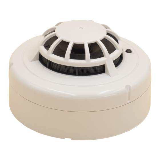
Figure 3: 2351TEM Photo
/ Thermal Fire Detector
DETECTOR COVER
SCREEN
SENSING
CHAMBER
DETECTOR
BASE
© System Sensor 2004
I56-1721-011
Advertisement

Related Manuals for System Sensor 2351TEM


Summary of Contents for System Sensor 2351TEM
- Page 1 The model 2351TEM Photo-Thermal fire detector combines a state of the art optical sensing chamber with a thermistor to offer greater flexibility and higher immunity to nuisance alarms. The ability to plug these detectors into a variety of base options extends panel compatibility and The red led on the detector should latch into alarm within 40 seconds, and the control panel should activate into alarm.
- Page 2 Indirizzare del fumo verso il rivelatore oppure, preferibilmente, utilizzare un “detector tester” Il rivelatore d’incendio ottico-termico modello 2351TEM, unisce lo stato dell’arte della rivelazione ottica del fumo alla misura del calore, attuata (prodotti No Climb Products Ltd od equivalenti) seguendo attentamente le istruzioni fornite dal mediante termistore, per offrire grande flessibilità...
- Page 3 Térmico 2351TEM servicio. Anule el sistema para evitar alarmas no deseadas. Antes de instalar los detectores, lea detenidamente la Guía de Sistemas Convencionales de Detección de Incendios de System Sensor, que le Compruebe el detector como sigue: proporcionará información detallada acerca de la distancia, ubicación, tipo de zonas y aplicaciones especiales del detector. Pueden obtenerse Método de Humo...
- Page 4 Meldergruppen Alarmweiterleitung ab um unerwünschte Alarmmeldungen während der Wartung zu unterdrücken. Bevor Sie mit der Installation der Brandmelder beginnen, lesen Sie bitte die sorgfältig die System Sensor Anleitung zum Umgang mit Rauch- und Prüfen Sie den Melder wie folgt: Wärmemeldern, in der wichtige Informationen zum Melderabstand, der Anordnung, der Überwachungsfläche sowie der Verdrahtung und Anwendung enthalten sind.