Table of Contents
Advertisement
nordictrack.com
Model No. NTL79020.1
Serial No.
Write the serial number in the space
above for reference.
Serial
Number
Decal
ACTIVATE YOUR
WARRANTY
To register your product and
activate your warranty today,
go to my.nordictrack.com.
CUSTOMER CARE
For service at any time, go to
nordictrackservice.com.
Or call 1-800-TO-BE-FIT
(1-800-862-3348)
Mon.–Fri. 6 a.m.–6 p.m. MT
Sat. 8 a.m.–12 p.m. MT
Please do not contact the store.
CAUTION
Read all precautions and instruc-
tions in this manual before using
this equipment. Save this manual
for future reference.
USER'S MANUAL
Advertisement
Table of Contents

Related Manuals for NordicTrack Elite 700 NTL79020.1


Summary of Contents for NordicTrack Elite 700 NTL79020.1
- Page 1 Serial Number Decal ACTIVATE YOUR WARRANTY To register your product and activate your warranty today, go to my.nordictrack.com. CUSTOMER CARE For service at any time, go to nordictrackservice.com. Or call 1-800-TO-BE-FIT (1-800-862-3348) Mon.–Fri. 6 a.m.–6 p.m. MT Sat. 8 a.m.–12 p.m. MT Please do not contact the store.
-
Page 2: Table Of Contents
305284 NORDICTRACK and IFIT are registered trademarks of ICON Health & Fitness, Inc. Google Maps is a trademark of Google LLC. The Bluetooth word mark and logos are registered trademarks of Bluetooth SIG, Inc. and are ®... -
Page 3: Important Precautions
5. The treadmill is intended for home use only. To purchase a surge suppressor, see your Do not use the treadmill in any commercial, local NORDICTRACK dealer, call the tele- rental, or institutional setting. phone number on the front cover of this manual, or see your local electronics store. - Page 4 19. Always stand on the foot rails when starting able to safely lift 45 lbs. (20 kg) to move the or stopping the walking belt. Always hold the treadmill. handrails while using the treadmill. 26. When folding or moving the treadmill, make 20.
- Page 5 STANDARD SERVICE PLANS...
-
Page 6: Before You Begin
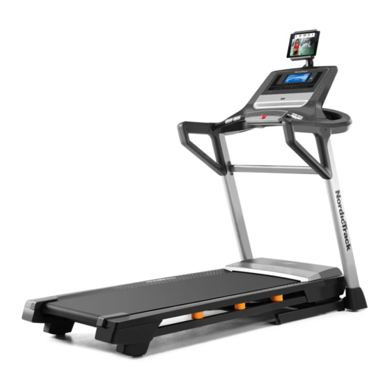
BEFORE YOU BEGIN Thank you for selecting the new NORDICTRACK manual. To help us assist you, note the product model ® ELITE 700 treadmill. The ELITE 700 treadmill provides number and serial number before contacting us. The an impressive selection of features designed to make model number and the location of the serial number your workouts at home more effective and enjoyable. -
Page 7: Part Identification Chart
PART IDENTIFICATION CHART Use the drawings below to identify small parts used for assembly. The number in parentheses below each draw- ing is the key number of the part, from the PART LIST near the end of this manual. The number following the key number is the quantity used for assembly. -
Page 8: Assembly
To avoid damaging parts, do not use power tools. • To identify small parts, see page 7. 1. Go to my.nordictrack.com on your computer and register your product. • documents your ownership • activates your warranty •... - Page 9 2. Make sure that the power cord is unplugged. Remove the tie securing the Upright Wire (81) to the front of the Base (94). Next, identify the Right Upright (90). Have a second person hold the Right Upright near the Base (94).
- Page 10 4. Hold the Right Upright (90) against the Base (94). Make sure not to pinch the Upright Wire (81). Attach the Right Upright (90) and a Wheel (101) with two 3/8" x 2 1/4" Screws (7), a 3/8" x 1 1/4" Screw (63), a 3/8"...
-
Page 11: Of The Cover Brackets (18) Into The Slot (F) In The
6. See the left drawing. Insert the tab (E) on one of the Cover Brackets (18) into the slot (F) in the Left Upright (89), and attach the Cover Bracket with two #8 x 1/2" Screws (1). See the right drawing. Attach the other Cover Bracket (18) to the Right Upright (90) as described above. - Page 12 8. Identify the right handrail assembly (I). Remove and discard the two indicated screws (J). Next, carefully raise the Pulse Crossbar (93) enough to allow you to slide the Handrail (86) onto the console base assembly (G). See the inset drawing. The Cover Bracket (18) should slide into the indicated space (K) in the hand- rail assembly.
- Page 13 10. With the help of a second person, hold the console assembly (L) near the console base assembly (G). Connect the wires (M) from the console base assembly (G) to the wires (N) from the console assembly (L). The connectors should slide together easily and snap into place.
- Page 14 12. Attach the Small Console Cover (27) with two #8 x 3/4" Screws (2); do not overtighten the Screws. Note: Use the outer two holes in the underside of the console base assembly (G). 13. Tighten the two 5/16" x 3/4" Screws (8). Then, tighten four #8 x 3/4"...
- Page 15 14. Firmly tighten the two 5/16" x 2 1/2" Screws (28) on each side of the handrail assembly (only one side is shown). Next, identify the Right Handrail Cover (26). Insert the tab (Q) on the Right Handrail Cover into the right handrail assembly (I) in the loca- tion shown.
- Page 16 16. Note: If the treadmill is assembled on a smooth surface, it may roll forward in this step. Remove the two 5/16" x 3/4" Patch Screws (4) from the Latch Crossbar (41). Raise the Frame (56) to the upright position. Have a second person hold the Frame until step 18 is completed.
- Page 17 18. Remove the 5/16" Nut (34) and the 5/16" x 2 1/4" Bolt (3) from the bracket on the Latch Crossbar (41). Align the upper end of the Storage Latch (53) with the bracket on the Latch Crossbar (41), and insert the 5/16" x 2 1/4" Bolt (3) through the bracket and the Storage Latch.
- Page 18 20. Press the two tabs (not shown) on the Tablet Holder (31) into the slots (W) in the console assembly (L). Then, attach the Tablet Holder (31) with four Start First M4 x 16mm Machine Screws (32). Note: Start the two top Screws first, and then start the two bottom Screws.
-
Page 19: How To Use The Treadmill
HOW TO USE THE TREADMILL HOW TO CONNECT THE POWER CORD more amps. To avoid overloading the circuit, do not plug other electrical devices, except for low- Use a Surge Suppressor power devices such as cell phone chargers, into the surge suppressor or into an outlet on the same Your treadmill, like other electronic equipment, can be circuit. - Page 20 CONSOLE DIAGRAM FEATURES OF THE CONSOLE To turn on the power, see page 21. To use the man- ual mode, see page 21. To use an onboard workout, see page 23. To connect your tablet to the console, The treadmill console offers a selection of features see page 25.
- Page 21 HOW TO TURN ON THE POWER If you press the Start button, the walking belt will begin to move at a low speed. As you exercise, IMPORTANT: If the treadmill has been exposed to change the speed of the walking belt as desired by cold temperatures, allow it to warm to room tem- pressing the Speed increase and decrease but- perature before you turn on the power.
- Page 22 6. Measure your heart rate if desired. • The incline level of the treadmill • The number of vertical feet you have climbed You can measure your heart rate using either the handgrip heart rate monitor or a compatible heart rate monitor.
- Page 23 8. When you are finished exercising, remove the 3. Start the workout. key from the console. Press the Start button or the Speed increase button Step onto the foot rails, press the End/Summary to start the workout. A moment after you press the button, and adjust the incline of the treadmill to button, the treadmill will automatically adjust to the zero.
- Page 24 Note: The calorie goal is an estimate of the 4. Follow your progress with the displays. number of calories that you will burn during the workout. The actual number of calories See step 5 on page 21. If you select an onboard that you burn will depend on various factors workout, the display will show the time remaining such as your weight.
- Page 25 HOW TO CONNECT YOUR TABLET TO THE 3. Connect your tablet to the console. CONSOLE Press the iFit Sync button on the console; the The console supports Bluetooth connections to tab- console pairing number will appear in the display. lets via the iFit–Smart Cardio Equipment app and to Then, follow the instructions in the iFit–Smart compatible heart rate monitors.
- Page 26 HOW TO CONNECT YOUR HEART RATE MONITOR THE SETTINGS MODE TO THE CONSOLE The console features an information mode that keeps The console is compatible with all Bluetooth Smart track of treadmill information and allows you to person- heart rate monitors. alize console settings.
- Page 27 THE OPTIONAL CHEST HEART RATE MONITOR HOW TO ADJUST THE CUSHIONS Whether your The treadmill features a cushioning system that goal is to reduces the impact as you walk or run on the treadmill. burn fat or to strengthen your To adjust the cushions, first remove the key from the cardiovascular console and unplug the power cord.
-
Page 28: Fcc Information
FCC INFORMATION This console has been tested and found to comply with the limits for a Class B digital device, pursuant to part 15 of the FCC Rules. These limits are designed to provide reasonable protection against harmful interference in a residential installation. This equipment generates, uses, and can radiate radio frequency energy and, if not installed and used in accordance with the instructions, may cause harmful interference to radio communications. -
Page 29: How To Fold And Move The Treadmill
HOW TO FOLD AND MOVE THE TREADMILL HOW TO FOLD THE TREADMILL HOW TO MOVE THE TREADMILL To avoid damaging the treadmill, adjust the incline Before moving the treadmill, fold it as described at the to zero before you fold the treadmill. Then, remove left. -
Page 30: Maintenance And Troubleshooting
MAINTENANCE AND TROUBLESHOOTING MAINTENANCE c. Check the power switch located on the treadmill frame near the power cord. If the switch protrudes Regular maintenance is important for optimal per- as shown, the switch has tripped. To reset the formance and to reduce wear. Inspect and properly power switch, wait for five minutes and then press tighten all parts each time the treadmill is used. - Page 31 SYMPTOM: The walking belt slows when walked on d. If the walking belt still slows when walked on, see the front cover of this manual. a. Use only a surge suppressor that meets all of the SYMPTOM: The walking belt is off-center or slips specifications described on page 19.
- Page 32 SYMPTOM: The tablet holder does not stay in place a. Rotate the tablet holder (B) until it faces backward. Then, tighten the indicated screw (C) slightly until the tablet holder stays in place when it is rotated to the desired position.
-
Page 33: Exercise Guidelines
EXERCISE GUIDELINES Burning Fat—To burn fat effectively, you must exer- WARNING: cise at a low intensity level for a sustained period of Before beginning this time. During the first few minutes of exercise, your or any exercise program, consult your physi- body uses carbohydrate calories for energy. -
Page 34: Part List
PART LIST Model No. NTL79020.1 R0919A Key No. Qty. Description Key No. Qty. Description #8 x 1/2" Screw 9/32" Plastic Bushing #8 x 3/4" Screw 3/8" Plastic Bushing 5/16" x 2 1/4" Bolt Storage Latch 5/16" x 3/4" Patch Screw Drive Motor #10 Star Washer Motor Belt... - Page 35 Key No. Qty. Description Key No. Qty. Description Wheel Pulse Cover Key/Clip 1/4" Washer Console Base Frame Plastic Snap Cable Tie Console Frame Upright Crossbar – User’s Manual Incline Motor Spacer Note: Specifications are subject to change without notice. For information about ordering replacement parts, see the back cover of this manual.
-
Page 36: Exploded Drawing
EXPLODED DRAWING A Model No. NTL79020.1 R0919A... - Page 37 EXPLODED DRAWING B Model No. NTL79020.1 R0919A...
- Page 38 EXPLODED DRAWING C Model No. NTL79020.1 R0919A...
- Page 39 EXPLODED DRAWING D Model No. NTL79020.1 R0919A...
-
Page 40: Ordering Replacement Parts
ORDERING REPLACEMENT PARTS To order replacement parts, please see the front cover of this manual. To help us assist you, be prepared to provide the following information when contacting us: • the model number and serial number of the product (see the front cover of this manual) •...
Need help?
Do you have a question about the Elite 700 NTL79020.1 and is the answer not in the manual?
Questions and answers
(nordictrack elite 700, model# NTL79020.1 ) the treadmill screen only shows the text "go to ifit.com/activate" and no other buttons do anything. when i did go to the website and downloaded the ifit app and connected the device, it was still stuck in that screen. what's weird is that i've had this treadmill for a long time and have never had to get the app before, so i'm not sure why it suddenly showed up
The NordicTrack Elite 700 treadmill model NTL79020.1 displays "go to ifit.com/activate" and remains unresponsive because it requires activation through the iFit service before it can be used. This is part of the initial setup process.
This answer is automatically generated