
Related Manuals for LUCCI AIRFUSION COMMAND II Series


Summary of Contents for LUCCI AIRFUSION COMMAND II Series
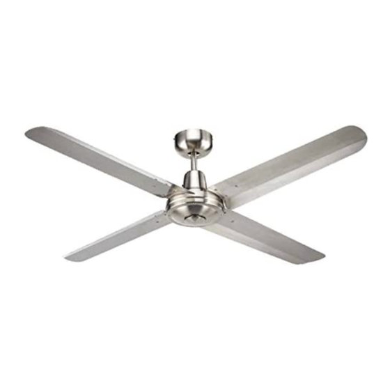
- Page 1 CEILING FAN MANUAL INSTALLATION OPERATION MAINTENANCE WARRANTY INFORMATION LUCCI AIRFUSION COMMAND II CEILING FAN CAUTION READ INSTRUCTIONS CAREFULLY FOR SAFE INSTALLATION AND FAN OPERATION. V1.1...
-
Page 2: Congratulations On Your Choice
CONGRATULATIONS ON YOUR CHOICE CONGRATULATIONS, on purchasing a quality Lucci ceiling fan. Lucci, a 100% Australian owned company has been developing ceiling fans since 1980, and over those years has introduced innovations to suit Australia’s unique environment and customer needs. -
Page 3: Important Notes
IMPORTANT NOTES Your warranty will be void if a solid-state dimmer type fan controller or other band wall controller is used. ONLY use the wall controller supplied. CONTROL With non-standard controllers, there is a strong possibility that the ceiling fan motor will produce an unpleasant loud humming noise. -
Page 4: Before Installation
BEFORE INSTALLATION • Unpack your ceiling fan carefully. • Remove all parts and hardware. • Place fan motor on a cloth or soft surface to avoid damaging the finish. • Verify that all parts are present before starting assembly. And check the packaging carefully for missing parts. -
Page 5: Installation Instructions
INSTALLATION INSTRUCTIONS FAN ASSEMBLY TOOLS REQUIRED Phillips head screw driver Flat head screw driver Pair of pliers Adjustable Spanner Step ladder Wire cutter Wiring, supply cable as required by AS/NZS 3000 wiring code. NOTE: It is recommended you must attach the blades to the motor housing BEFORE mounting the motor to the ceiling. -
Page 6: Installing The Fan
INSTALLING THE FAN 1. The ceiling fan must be installed in a location so that the blades are at least 2.1 meters above the floor, and 300mm spacing from the tip of the blade to the nearest objects or walls. 2. - Page 7 ELECTRICAL WIRING DIAGRAM (AIRFUSION CEILING FAN) INSTALLING THE FAN WARNING: FOR YOUR SAFETY ALL ELECTRICAL CONNECTIONS MUST BE UNDERTAKEN BY A LICENCED ELECTRICIAN NOTE: AN ADDITIONAL ALL POLE DISCONNECTION SWITCH MUST BE INCLUDED IN THE FIXED WIRING. FIG. 5 NOTE: Wiring diagram includes the light kit wiring. The light wiring diagram and switch is omitted when no light kit is use with the ceiling fan.
- Page 8 USING YOUR CEILING FAN INSTALLING THE FAN FAN WALL CONTROL Your ceiling fan is controlled via the rotary switch (fan) and rocker switch (light) via the wall controller. Refer to below figures: SWITCH POSITION DESCRIPTION (ARROW POINTING) OFF – FAN IS OFF 1 –...
- Page 9 REVERSING SWITCH Your ceiling can operate either summer or winter mode. SUMMER Mode: The reverse switch shall be in the “down” (SUMMER) position to make the fan rotate in an anticlockwise direction. The airflow will be directed downwards, for cooling in summer. WINTER Mode: The reverse switch shall be in the “up”...
- Page 10 LIGHT KIT Installation (Light kit - optional) Note: Light kit must be installed by a Licensed Electrician. FIG. 9 Unscrew the decorative cover plate from the bottom of motor housing. Carefully pull the L wire and N wire for light out from shaft. Insert wires through the light connector (1).
-
Page 11: Warranty & Service
BALANCING / WOBBLYING TROUBLE SHOOTING INSTALLING THE FAN Please note that all ceiling fans are not the same, even in the same model—some may move more or less than others. Movement of a couple of centimetres is quite acceptable and does not suggest the fan will fall down or have an faults. -
Page 12: Normal Wear And Tear
WOBBLE Ceiling fans tend to move during operation due to the fact that they are not generally rigidly mounted—if they were, they could generate excessive ceiling vibration and stress on their mountings. Movement of a couple of centimetres is quite acceptable and does not suggest the fan will fall down or is faulty. - Page 13 RIPPLE CONTROL (Extract from Hunter Pacific International) Throughout Australia, but in particular Sydney and other parts of NSW and Queensland, electricity distributors use a remote control and switching system that is commonly called ripple control. Ripple control has existed for many years and is used for controlling demand and implementing different customer tariffs. Our electricity supply is 240 Volts AC 50 Hertz.
-
Page 14: Troubleshooting Checklist
WARNING: THE CEILING MUST BE SWITCHED OFF, BEFORE TROUBLE SHOOTING IS PERFORMED. TECHINCAL INFORMATION Rated Rated Power Ceiling Fan model Voltage (motor) LUCCI AIRFUSION COMMAND II – 56’ blade 220-240 VAC LUCCI AIRFUSION COMMAND II – 52’ blade 220-240 VAC LUCCI AIRFUSION COMMAND II – 48’ blade 220-240 VAC... -
Page 15: Warranty Conditions
WARRANTY CONDITIONS This product is guaranteed against electrical defects in material or manufacturing workmanship for faults when under normal domestic/residential conditions for a certain period of time from the date of purchase. This warranty covers parts and labour costs for the motor subject to the following conditions: 1. - Page 16 electrical motors have some audible noise. Allow at least eight hours of operation to allow the bearings to properly seat. The fan, especially when set on low, may feel warm to touch – this is not a fault. If excessive heat is generated a service call may be required. Fan noises can vary due to slight power fluctuations and mains frequency signals for off –...
- Page 17 Lucci cannot be held responsible for any repair other than those carried out by it or one of its Authorised Service Agents. Please keep this warranty information in a safe place. This information must be produced in the event of service being required.
- Page 18 CEILING FAN WARRANTY DETAIL LUCCI WARRANTY HOTLINE- 1800 602 243 Retain AND Fill this form and keep it for your personal records and warranty purposes NAME………………………………………………………………………………… ADDRESS…………………………………………………………………………… ……………………………………………………POSTCODE…………………… MODEL NUMBER…………………………………………………………………… (PO# or DATECODE Sticker here) PO NUMBER or DATECODE ………………………………………………………...
Need help?
Do you have a question about the AIRFUSION COMMAND II Series and is the answer not in the manual?
Questions and answers