Table of Contents
Advertisement
Available languages
Available languages
Advertisement
Chapters
Table of Contents

Related Manuals for THERMOBILE Bio Energy Series


Summary of Contents for THERMOBILE Bio Energy Series
- Page 2 /h........... 1000 Volt/Hz/Amp........... 230/50/1,2 Prod. code..........41.906.150 Fabr.year 2006 Serial nr: 49.0051 Made by THERMOBILE Ind. B.V. Breda, Holland - 1 - - 2 - - 4 - - 3 - - 5 - 40.020.944 - rev. 05 - 2015...
- Page 3 - 7 - - 8 - Bio Energy series 40.020.944 - rev. 05 - 2015...
- Page 4 Nederlands ..........5 English ............16 Deutsch............26 Français .............37 Español............49 Русский язык..........61 40.020.944 - rev. 05 - 2015 Bio Energy series...
-
Page 5: Table Of Contents
Zorg dat u de volgende gegevens bij de hand hebt: type en serie nummer van de kachel. Garantie en aansprakelijkheid Voor garantie en aansprakelijkheid, zie algemene garantiebepalingen. Bio Energy series 40.020.944 - rev. 05 - 2015... -
Page 6: Veiligheidsinstructies
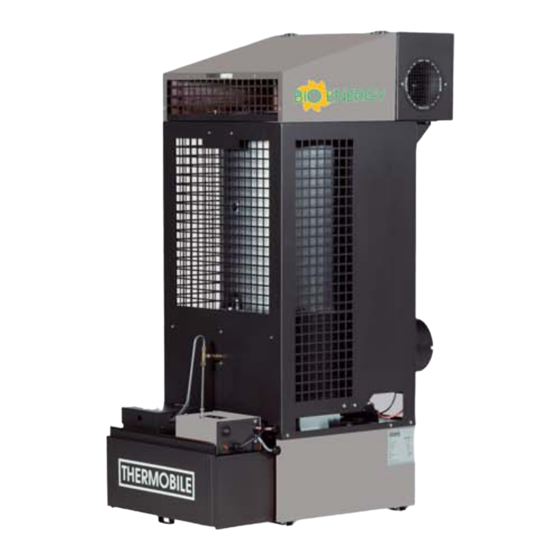
De eerste elektromotor drijft een vorstvrij houden van hallen, opslagloodsen branstofpomp aan, die de brandstof uit de en magazijnen en voor de verwarming van brandstoftank oppompt. garagewerkplaatsen. 40.020.944 - rev. 05 - 2015 Bio Energy series... - Page 7 Aansluitsnoer de brandstoftank. Een overloopbeveiliging schakelt de brandstofpomp uit als de branderschaal overloopt. Hoofdcomponenten stationaire plantaardige olie of biodiesel kachel (fig. 3) Deksel Schoorsteenaansluiting Branderkamer Aansluiting voor warmeluchtventilator Bio Energy series 40.020.944 - rev. 05 - 2015...
-
Page 8: Voorbereidingen
8. Laat de brandende prop op de alleen de volgende oliesoorten branderschaal vallen. verbrand worden: 9. Sluit het hitteschild. • Plantaardige olie 10. Sluit de warmteverdeler. • Biodiesel 40.020.944 - rev. 05 - 2015 Bio Energy series... -
Page 9: Gebruik
Deze ventilator koelt de kachel tot deze voldoende is afgekoeld (na 10 tot 30 minuten). De verbrandingsluchtventilator blijft net zo lang draaien tot de verbranding beëindigd is. Bio Energy series 40.020.944 - rev. 05 - 2015... -
Page 10: Onderhoud
Reinig de schoorsteenklep in het T-stuk, zie fig. 7 (A). Dealer De aanbevolen trek is 1.5 mmwk (0.06” water column). Reinig het T-stuk van de schoorsteen, zie “schoor- steenklep reinigen”. Controleer de bedrading van de kachel. 40.020.944 - rev. 05 - 2015 Bio Energy series... - Page 11 (D) met de voorkant van de schep. Zorg dat de gaten in de wand van de verdamper open blijven voor verbrandingslucht. 6. Verwijder eventuele roetdeeltjes van de bodem van de verdamper. Bio Energy series 40.020.944 - rev. 05 - 2015...
-
Page 12: Storingen
Installeer de brandstoftank in de omgekeerde volgorde. STORINGEN Zorg dat de stroom is ingeschakeld en de brandstoftank vol is, voordat u begint met storingzoeken. WAARSCHUWING Sluit de elektrische stroom af tijdens reparatie! 40.020.944 - rev. 05 - 2015 Bio Energy series... - Page 13 Er is onvoldoende toe- Reinig de gaten in de ver- Gebruiker voer van verbran-dings- damper, zie fig. 4(D). lucht. Controleer de werking van de Dealer verbrandingsluchtventilator. Bio Energy series 40.020.944 - rev. 05 - 2015...
- Page 14 De brandstofpomp Zie storingen: 3, 6 en 14. draait niet en de con- trolelamp brandt niet, terwijl de kachel voorverwarmd is en de schakelaar in de stand “1” of “2” staat. 40.020.944 - rev. 05 - 2015 Bio Energy series...
-
Page 15: Reserveonderdelen
2. Schuif de schoorsteenpijp op het T-stuk. schoorsteen. 3. Schroef de schoorsteenpijp met drie schroeven vast op het T-stuk. Diameter schoorsteen VOORZICHTIG Bio Energy 1 De schoorsteen moet aan de onderstaande eisen voldoen. 150 mm Bio Energy series 40.020.944 - rev. 05 - 2015... -
Page 16: Eg-Verklaring Van Overeenstemming
Nederlands EG-VERKLARING VAN OVEREENSTEMMING De EG-Verklaring van overeenstemming kunt u vinden op www.thermobile.nl. 40.020.944 - rev. 05 - 2015 Bio Energy series... - Page 17 Make sure you have the following data at hand: type and serial number of the heater. Warranty and liability For warranty and liability, see general warranty regulations. Bio Energy series 40.020.944 - rev. 05 - 2015...
-
Page 18: Safety Instructions
The stationary used oil fired hot air heater has been designed for heating of workshops at mechanization companies, heating and frost protection of halls, transit sheds and warehouses and heating of garage workshops. 40.020.944 - rev. 05 - 2015 Bio Energy series... - Page 19 The overflow protection switches off the fuel pump when the burner dish overflows. Bio Energy series 40.020.944 - rev. 05 - 2015...
-
Page 20: Preparations
2: High pump speed used in the stationary used (vegetable oil or biodiesel) heaters: Control light Low pump speed Control light High pump speed • Vegetable oil Pump regulator • Biodiesel Connection cable 40.020.944 - rev. 05 - 2015 Bio Energy series... -
Page 21: Use
7. Form a paper pellet and light it. 8. Drop the burning pellet on the burner dish. 9. Close the heat shield. 10. Close the heat distributor. Bio Energy series 40.020.944 - rev. 05 - 2015... -
Page 22: Maintenance
Clean the flue stack valve in the T-piece, see fig. 7 (A). Dealer The recommended draught is 1.5 mmwk (0.06” water column). Clean the flue stack T-piece, see "cleaning the flue stack valve". Check the heater's wiring. 40.020.944 - rev. 05 - 2015 Bio Energy series... -
Page 23: Faults
(B) and the vaporisation Switch off power during chamber (D with the front of the shovel. maintenance! Ensure that the holes in the combustion chamber wall remain open for combustion air supply. Troubleshooting table Bio Energy series 40.020.944 - rev. 05 - 2015... - Page 24 Check the fuel pump for dirt. Dealer The fuel supply pipe is Clean the fuel supply pipe, User blocked: The fuel flows see fig. 3 (O). back into the fuel tank through the return pipe. 40.020.944 - rev. 05 - 2015 Bio Energy series...
- Page 25 Check all connections in the User low. flue. Reduce the number of User bends. Heighten the flue. User Isolate the flue outside the User building. Check the flue, see "flue". User Bio Energy series 40.020.944 - rev. 05 - 2015...
-
Page 26: Spare Parts
See for technical specifications table C in the appendix of this booklet. SPARE PARTS Before use we advise you to have spare parts in store, see table B in the appendix of this manual. 40.020.944 - rev. 05 - 2015 Bio Energy series... -
Page 27: Installing Accessories
5. Place a cap (D) at the end of the flue. Diameter flue Bio Energy 1 150 mm EC DECLARATION OF CONFORMITY For the EC declaration of conformity, go to www.thermobile.nl. Bio Energy series 40.020.944 - rev. 05 - 2015... - Page 28 Sie bei Ihrem Händler oder Hersteller. Bitte halten Sie die folgenden Angaben bereit: Typ- und Seriennummer des Heizers. Garantie und Haftung Näheres zu Garantie und Haftung entnehmen Sie bitte den Allgemeinen Garantiebestimmungen. 40.020.944 - rev. 05 - 2015 Bio Energy series...
-
Page 29: Sicherheitshinweise
Der feststehende, mit Altöl betriebene Diese feststehenden, mit Altöl (Rübsamenöl Warmluftheizer ist zum Beheizen von oder Biodiesel) betriebenen Heizer werden Mechaniker-Werkstätten, zum Beheizen und direkt befeuert, verfügen über einen zum Frostschutz von Hallen, Bio Energy series 40.020.944 - rev. 05 - 2015... -
Page 30: Deutsch
Defekts schaltet der Pumpenthermostat die Schaufel Kraftstoffpumpe ab. Die Kraftstoffpumpe wird bei Ausschalten des Heizers ebenfalls ausgeschaltet. Der Heißluftventilater läuft so lange weiter, bis der Ventilatorthermostat den Ventilator nach ausreichender Abkühlung ausschaltet. 40.020.944 - rev. 05 - 2015 Bio Energy series... -
Page 31: Vorbereitungen
Vorbereiten der Installation 2. Entfernen Sie das Verpackungsmaterial 1. Stellen Sie die von den Bauteilen der Brennkammer. Kraftstoffpumpensteuerung auf "1" (siehe Abbildung 5 (A)). 2. Öffnen Sie die Tankverriegelung (siehe Abbildung 3 (P). Bio Energy series 40.020.944 - rev. 05 - 2015... -
Page 32: Anwendung
2. Stellen Sie den Pumpenregler für die ersten 20 bis 30 Minuten auf "1" (siehe Abb. 5. (A)). 3. Stellen Sie den Pumpenregler nach Erreichen der Höchsttemperatur auf "2" (siehe Abb. 5. (A). 40.020.944 - rev. 05 - 2015 Bio Energy series... -
Page 33: Wartung
Reinigen Sie das Schornsteinventil im T-Stück (siehe Händler Abb. 7. (A)). Der empfohlene Zug liegt bei 1,5 mm Wassersäule (0,06'' Wassersäule). Reinigen Sie das Schornsteinventil im T-Stück (siehe "Reinigung des Schornsteinventils"). Überprüfen Sie die Anschlüsse des Heizers. Bio Energy series 40.020.944 - rev. 05 - 2015... -
Page 34: Störungen
6. Befreien Sie die Kraftstoffkammerboden von Ruß. 7. Reinigen Sie die Kraftstoffleitung mit einer Bürste (Innendurchmesser 8,5 mm (0,33'', siehe Abb. (O)). 8. Der Einbau aller Bestandteile erfolgt in umgekehrter Reihenfolge. 40.020.944 - rev. 05 - 2015 Bio Energy series... - Page 35 Temperatur noch nicht Den Heizer längere Zeit mit Anwen- erreicht. dem Schalter auf "1" brennen lassen (siehe Abb. 5. (A)). Pumpenthermostat austau- Händler schen. Der Heißluftthermostat Heißluftthermostat austau- Händler ist defekt. schen. Bio Energy series 40.020.944 - rev. 05 - 2015...
- Page 36 (siehe Abb. 3. (Q)). liert oder defekt. Den Begrenzer austauschen Händler (siehe Abb. 3. (Q)). 14 Der Überlaufschutz ist Die Überlaufschüssel, die Anwen- mit Rübsamenöl oder Brennschüssel und den Ver- Biodiesel gefüllt. dampferboden reinigen. 40.020.944 - rev. 05 - 2015 Bio Energy series...
-
Page 37: Ersatzteile
Ihnen, die entsprechenden Ersatzteile vorrätig zu haben. Siehe Tabelle B im Anhang dieser Bedienungsanleitung. TECHNISCHE INFORMATION • Für die Technischen Daten wird auf Tabelle C im Anhang dieser Bedienungsanleitung verwiesen. Bio Energy series 40.020.944 - rev. 05 - 2015... -
Page 38: Installation Von Zubehör
4. Montieren Sie die folgenden Leitungsteile. 5. Bringen Sie eine Regenhaube (A) am Ende des Schornsteins. Durchmesser Schornstein Bio Energy 1 150 mm EG-KONFORMITÄTSERKLÄRUNG Die EG-Konformitätserklärung finden Sie unter www.thermobile.nl. 40.020.944 - rev. 05 - 2015 Bio Energy series... - Page 39 Assurez-vous de disposer des informations suivantes : le type de générateur et son numéro de série Garantie et responsabilité Pour des conditions de garantie, voir les conditions générales de garantie. Bio Energy series 40.020.944 - rev. 05 - 2015...
-
Page 40: Consignes De Sécurité
Principe de fonctionnement Les générateurs alimentés à l'huile (à l'huile de colza ou au biodiesel) pour utilisation fixe sont équipés de trois moteurs électriques. 40.020.944 - rev. 05 - 2015 Bio Energy series... -
Page 41: Français
La protection de trop plein coupe la pompe à combustible lorsque le plateau brûleur déborde. Bio Energy series 40.020.944 - rev. 05 - 2015... -
Page 42: Préparations
1. Positionnez la commande de pompe à combustible sur "1", voir fig. 5 (A). 2. Poussez le boulon du réservoir vers le haut, voir fig. 3 (P). 3. Ouvrez l'écran thermique, voir fig. 4 (A). 40.020.944 - rev. 05 - 2015 Bio Energy series... - Page 43 "1" pendant les 20 à 30 premières minutes, voir fig. 5(A). 3. Positionnez le régulateur de la pompe sur "2" lorsque la température maximum est atteinte, voir fig. 5 (A). Bio Energy series 40.020.944 - rev. 05 - 2015...
-
Page 44: Emploi
ENTRETIEN Tableau d’entretien Utiliser le tableau dans ce manuel pour enregistrer l'entretien effectué après chaque saison d'hiver. Avertissement Nettoyez toujours la chambre de combustion avant de démarrer le générateur. 40.020.944 - rev. 05 - 2015 Bio Energy series... - Page 45 Le tirage recommandé est de 1,5 mmce (0,06” de colonne d'eau). Nettoyez la pièce en T du tuyau de cheminée, voir "net- toyage de la vanne de tuyau de cheminée". Bio Energy series 40.020.944 - rev. 05 - 2015...
- Page 46 2. Nettoyez la bague de vaporisation (C) avec une brosse en acier. 3. Retirez le plateau brûleur (F) avec le crochet de la pelle (J). 4. Nettoyez le plateau brûleur avec un grattoir. 40.020.944 - rev. 05 - 2015 Bio Energy series...
-
Page 47: Erreurs
6. Installez le réservoir à combustible en ordre inverse. ERREURS Assurez-vous que l'alimentation électrique est activée et que le réservoir à combustible est plein avant de commencer le dépannage. Avertissement Couper l'alimentation pendant l'entretien! Bio Energy series 40.020.944 - rev. 05 - 2015... - Page 48 Le tuyau d'alimentation Nettoyez le tuyau d'alimenta- Utilisateur en combustible est bou- tion en combustible, voir fig. ché : le combustible 3 (O). retourne dans son réservoir via le tuyau de retour. 40.020.944 - rev. 05 - 2015 Bio Energy series...
- Page 49 "tuyau de cheminée". Ajustez le tuyau de cheminée selon un tirage correct (voir le tableau d'entretien 5.1) avec le contrepoids sur la vanne (fig. 7) Bio Energy series 40.020.944 - rev. 05 - 2015...
- Page 50 15 Il y a trop d'huile de Réduisez la quantité d'huile Utilisateur un bourdonnement. colza ou de biodiesel au de colza ou de biodiesel. démarrage. Voir défaillances : 10, 11 et 40.020.944 - rev. 05 - 2015 Bio Energy series...
-
Page 51: Pièces Détachées
T. 150 mm Précaution Le tuyau de cheminée doit respecter DÉCLARATION DE CONFORMITÉ les impératifs suivants. Pour la déclaration de conformité CE, rendez-vous sur le site www.thermobile.nl. Bio Energy series 40.020.944 - rev. 05 - 2015... - Page 52 ¡Desconecte siempre la alimentación Consulte los términos de garantía y eléctrica cuando realice trabajos de responsabilidad en las reglas generales de mantenimiento o reparaciones en el garantía. generador de aire caliente! 40.020.944 - rev. 05 - 2015 Bio Energy series...
-
Page 53: Español
¡Algunas superficies pueden estar calientes! Espere hasta que estos componentes se hayan enfriado lo suficiente antes de realizar el mantenimiento. Sugerencias y consejos para simplificar la realización de las tareas o acciones especificadas. Bio Energy series 40.020.944 - rev. 05 - 2015... - Page 54 Estos generadores de uso estacionario que utilizan aceite (de colza o biodiesel) son generadores de combustión directa con protección térmica y conexiones para una chimenea con cubierta para lluvia y un termostato en el recinto opcional. 40.020.944 - rev. 05 - 2015 Bio Energy series...
- Page 55 La bomba de combustible se desconecta oxígeno cuando se desconecta el generador. Pala El ventilador de aire caliente funciona hasta que el termostato lo desconecta cuando se haya enfriado lo suficiente. Bio Energy series 40.020.944 - rev. 05 - 2015...
- Page 56 2. Retire el embalaje de las piezas sueltas 5 (A). en la cámara de combustión. 2. Empuje hacia arriba el perno del depósito, véase la fig. 3 (P). 3. Abra el escudo térmico, véase la fig. 4 (A). 40.020.944 - rev. 05 - 2015 Bio Energy series...
- Page 57 5 (A). Durante el funcionamiento Caliente ¡No toque la chimenea ni la salida del soplador! ¡La chimenea y la salida del soplador se calientan durante el funcionamiento! Bio Energy series 40.020.944 - rev. 05 - 2015...
- Page 58 Limpie la válvula de la chimenea en la pieza en T, Distri- véase la fig. 7 (A). buidor El tiro recomendado es 1,5 mm de columna de agua (0,06” de columna de agua). 40.020.944 - rev. 05 - 2015 Bio Energy series...
- Page 59 2. Limpie el anillo de vaporización (C) con un cepillo de acero. 3. Retire el plato quemador (F) con el gancho de la pala (J). 4. Limpie el plato quemador con un rascador. Bio Energy series 40.020.944 - rev. 05 - 2015...
- Page 60 1. Retire el suministro de combustible (A). Advertencia 2. Saque la placa de conexión (B). ¡Desconecte la alimentación eléctrica 3. Quite el tapón (C) de la parte del chasis. durante el mantenimiento! Tabla de localización de averías 40.020.944 - rev. 05 - 2015 Bio Energy series...
- Page 61 Limpie el conducto de sumi- Usuario tro de combustible está nistro de combustible, véase obstruido: el combusti- la fig. 3 (O). ble regresa al depósito de combustible por el conducto de retorno. Bio Energy series 40.020.944 - rev. 05 - 2015...
- Page 62 Coloque una válvula en la Distribui- demasiado elevado o chimenea, consulte "Chime- irregular. nea". Ajuste la chimenea al tiro correcto (consulte la tabla de mantenimiento 5.1) con el contrapeso de la válvula (fig. 40.020.944 - rev. 05 - 2015 Bio Energy series...
- Page 63 Consulte los fallos: 10, 11 y Hay formación de Consulte los fallos: 8, 9, 10, hollín en la cámara 11 y 12. de combustión y en la chimenea. Bio Energy series 40.020.944 - rev. 05 - 2015...
- Page 64 La chimenea debe estar orientada hacia arriba. • La chimenea (o cualquier parte de ella) no puede colocarse horizontalmente. Un ángulo de 45° es aceptable. • No se permite alargar la conexión de la chimenea horizontalmente. 40.020.944 - rev. 05 - 2015 Bio Energy series...
- Page 65 свяжитесь со своим дилером или производителем. Позаботьтесь о том, чтобы под рукой имелись следующие данные: тип и серийный номер нагревателя. Гарантия и ответственность По вопросам гарантии и ответственности см. общие гарантийные условия. Bio Energy series 40.020.944 - rev. 05 - 2015...
- Page 66 Пиктограммы на стационарном нагревателе, работающем на рапсовом масле или биодизельном топливе (рис. 2) Данные о рапсовом масле или биодизельном топливе. Предупреждение о перегреве и выключении. Инструкция по эксплуатации. Инструкция по повторному зажиганию. 40.020.944 - rev. 05 - 2015 Bio Energy series...
-
Page 67: Введение
нагревателя и подается в место работающие на отработанном масле подогрева. (рапсовое масло или биодизельное Термостат насоса выключает топливный топливо), являются нагревателями с насос, когда в результате отказа прямым обогревом, теплозащитой и нагреватель перегревается. Bio Energy series 40.020.944 - rev. 05 - 2015... - Page 68 остывает, термостат вентилятора Q Защитный термостат выключает воздушный вентилятор. Основные компоненты горелки(fig. 4) (рис. 4) Взрывное окно Камера сгорания Колько парообразования Секция парообразования Вентилятор для подачи воздуха горения Чаша горелки G Переливная защита 40.020.944 - rev. 05 - 2015 Bio Energy series...
-
Page 69: Подготовка К Работе
По достижении чашой горелки 9. Проверьте поверхность пола: она требуемой температуры запускается должна составлять, по крайней мере, топливный насос, и загорается 36 м контрольная лампочка. 10. Установите дымоход (5,5 м и дождевой колпак). Bio Energy series 40.020.944 - rev. 05 - 2015... -
Page 70: Эксплуатация
горения работает до тех пор, пока продолжается горение. Описание Период Каждые Еженед Ежемес Ежегод ельно ячно но месяцев Почистите камеру сгорания. Спустите конденсат из топливного бака, если рапсовое масле или биодизельное топливо содержит воду. 40.020.944 - rev. 05 - 2015 Bio Energy series... - Page 71 камера сгорания не остынут. чтобы защитить камеру от коррозии. ОСТОРОЖНО Общие положения Не используйте нагреватель в жаркую погоду для сжигания ОСТОРОЖНО топлива. Отключайте электропитание при проведении техобслуживания. Для длительного хранения нагревателя: Bio Energy series 40.020.944 - rev. 05 - 2015...
-
Page 72: Неисправности
6. Установите топливный бак в обратном 8. Установите все детали в обратном порядке. порядке. Неисправности Перед поиском и устранением неисправностей убедитесь в том, что питание отключено и топливный бак наполнен. ОСТОРОЖНО Отключайте питание при проведении техобслуживания. 40.020.944 - rev. 05 - 2015 Bio Energy series... - Page 73 В топливном баке вода Почистите бак и Пользова или осадок. топливный фильтр, см. тель рис. 3 (F). Топливный насос не Установите переключатель Пользова включается. в положение 1, см. рис. 5 тель (А). Bio Energy series 40.020.944 - rev. 05 - 2015...
- Page 74 подачи воздуха замените его при горения не работает. необходимости. Недостаточная подача Почистите отверстия в Пользова воздуха горения. испарителе, см. рис. 4 (D). тель Проверьте работу Дилер вентиляторя для подачи воздуха горения. 40.020.944 - rev. 05 - 2015 Bio Energy series...
- Page 75 см. рис. 3 (Q). тель неправильно. Замените термостат, см. Дилер рис. 3 (Q). 14 Переливная защита Почистите чашу Пользова заполнена рапсовым переливной защиты, чашу тель маслом или горелки и дно испарителя. биодизельным топливом. Bio Energy series 40.020.944 - rev. 05 - 2015...
-
Page 76: Запасные Части
• Технические спецификации указаны в таблице С в приложении к данной Запасные части книге. До использования прибора мы советуем вам запастить запасными частями, см. таблицу В в приложении к данной книге. 40.020.944 - rev. 05 - 2015 Bio Energy series... -
Page 77: Установка Вспомогательного Оборудования
коньком крыши, по крайней мере, на 0,5 м. • Держите вертикальную часть сзади нагревателя как можно дольше, прежде чем выводить ее наружу через стенку. 4. Установите следующие детали трубы. 5. На конце дымохода поместите колпак (D). Bio Energy series 40.020.944 - rev. 05 - 2015... - Page 78 Description: Maintenance or Failure Action by Datum Beschreibung: Wartung oder Fehler Aktion durch Date Description: Entretien ou Erreur Action par Fecha Descripcíon Mantenimiento o fallo Accíon por Дата Описание: устранение неисправности Выполнено 40.020.944 - rev. 05 - 2015 Bio Energy series...
- Page 79 Description: Maintenance or Failure Action by Datum Beschreibung: Wartung oder Fehler Aktion durch Date Description: Entretien ou Erreur Action par Fecha Descripcíon Mantenimiento o fallo Accíon por Дата Описание: устранение неисправности Выполнено Bio Energy series 40.020.944 - rev. 05 - 2015...
- Page 80 Bio Energy 1 Verbrandings-schaal Échelle de combustion 41.900.521 Combustion scale Plato de combustión Verbrennungsschale Уровень горения 40.020.944 - rev. 05 - 2015 Bio Energy series...
- Page 81 горения с полным баком Verwarmde luchtstroom Flux d'air chaud /h 800 Heated airflow Flujo de aire calentado Warmluftstrom Поток нагретого воздуха Stroom Courant Current Corriente Strom Ток Lengte Longueur Length Longitud Länge Длина Bio Energy series 40.020.944 - rev. 05 - 2015...
- Page 82 ρ (15° C): 0.85 kg/dm • = 42.689 MJ/kg • = 45.5 MJ/kg • 1 kW = 860 kcal/h • 1 kW = 3413 Btu/h • 1 kW = 3.6 MJ/h 40.020.944 - rev. 05 - 2015 Bio Energy series...
- Page 83 All rights reserved. The available information has been prepared to a high level of care, but Thermobile Industries B.V. cannot be held liable for possible errors in the information or the consequences thereof. The information provided herein may not be reproduced and/or published in any form, by print, (electronically or mechanically) without the prior written authorisation of Thermobile Industries B.V.
Need help?
Do you have a question about the Bio Energy Series and is the answer not in the manual?
Questions and answers