Table of Contents
Advertisement
Quick Links
Advertisement
Table of Contents

Related Manuals for IC Realtime F Series


Summary of Contents for IC Realtime F Series
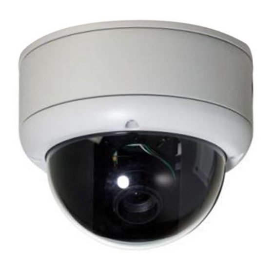
- Page 1 Vandal Proof IP Dome Camera User’s Manual V1.1.1...
- Page 2 Welcome Thank you for purchasing our IP camera! This user‟s manual is designed to be a reference tool for your system. Please read the following safeguard and warnings carefully before you use this series product! Please keep this user‟s manual well for future reference!
- Page 3 Important Safeguards and Warnings 1.Electrical safety All installation and operation here should conform to your local electrical safety codes. This series product uses DC 12V power. Please make sure your power sourcing equipment is right before you boots up the device. Before you replace the SD card, please unplug the power cable and then remove the shell We assume no liability or responsibility for all the fires or electrical shock caused by improper handling or installation.
- Page 4 Quick Start Guide Warranty Card Certificate Card...
-
Page 5: Table Of Contents
Table of Contents General Introduction ......................7 Overview ........................7 Features ........................7 Specifications ......................8 1.3.1 Performance ...................... 8 1.3.2 Function Specification ..................9 1.3.3 Factory Default Setup ..................11 Structure ..........................15 Multiple-function Composite Cable ............... 15 Framework and Dimension ................... 16 Bidirectional talk ..................... - Page 6 Login and Main Interface ..................27 FAQ ............................30...
-
Page 7: General Introduction
1 General Introduction 1.1 Overview This series IP camera integrates the traditional camera and network video technology. It adopts audio and video data collection, transmission together. It can connect to the network directly without any auxiliary device. This series IPC uses standard H.264 video compression technology and G.711a audio compression technology, which maximally guarantee the audio and video quality. -
Page 8: Specifications
To guarantee proper performance, please make sure the power sourcing device can supply at least 6.4W power for DB series product and 10W power for DBW series product. Log function Support PAL/NTSC Support system resource information and running status real-time display. -
Page 9: Function Specification
Video PAL:1-ch 1f/s~25f/s adjustable Recording NTSC:1-ch 1f/s~30f/s adjustable Speed IR Distance 10~20M(For IR series product) Max support 10 network users to monitor simultaneously TCP output capacity 75Mbps Network Capacity UDP output capacity 85Mbps <6W Power Consumption Power DC 12V Temperature -10℃~+50℃... - Page 10 After enabling manual record, no matter system is in schedule or Manual Record alarm status or not, system just begins recording. System automatically enables recording function when alarm Alarm Record occurred. When video changes, system automatically enables record Motion Detection Record operation.
-
Page 11: Factory Default Setup
12V power adapter One analog video output port One audio input port One audio output port 9-pin I/O Port Two alarm input port One alarm output port One network interface(RJ45 10M/100M self-adaptive Ethernet port) One red/green running status indication light. Others One RESET conversion cable IR light (For IR series product only) - Page 12 Watermark: DigitalCCTV Privacy Mask Never Time title Enable. OSD transparent :128 Channel title Enable. OSD transparent :128 Record Setup Channel Ch01 Pre-record 5 seconds. Time Setup Start Time 0:00:00 End Time 23:59:59 Record Period 1:Enable motion detection/alarm Snapshot Period 1: Enable motion detection/alarm Week Sunday...
- Page 13 Send email Disable PTZ activation Disable Event type: never Address: 0 Snapshoot Disable Video Detection Event type Motion detection Channel Ch01, Disable Sensitivity Time period setup Period: Start time 0:00:00 End time:23:59:59 Period 1:enable Week: Sunday Anti-dither 5 seconds General output Disable Alarm latch 10 seconds...
- Page 14 Quality Auto Auto reboot 2.00 each day maintain Auto delete Never old files Camera Property Channel Exposure Mode Auto Day/Night Mode Color Backlight Compensation Disable Auto Aperture Disable Disable White Balance Signal Type Internal input Mirror Disable Disable Flip Disable Disable Auto Registration Enable Disable...
-
Page 15: Structure
2 Structure 2.1 Multiple-function Composite Cable You can refer to the following figure for multiple-function composite cable information. See Figure 2-1 Figure 2-1 Please refer to the following sheet for detailed information. Port Name Function Connection Note Video output Output analog video signal. It can connect to the VIDEO OUT port TV monitor to view the video. -
Page 16: Framework And Dimension
Port Name Cable Name Note Color Alarm output port. It is to output the alarm signal to the alarm device. White ALARM_NO NO: normal open alarm output port. It works with the ALARM_COM port. It is to restore factory default setup. When the device is working properly, please Blue RESET... -
Page 17: Bidirectional Talk
Figure 2-3 2.3 Bidirectional talk 2.3.1 Device-end to PC-end Device Connection Please connect the speaker or the pickup to the first audio input port in the device rear panel. Then connect the earphone or the sound box to the audio output port in the PC. Login the Web and then enable the corresponding channel real-time monitor. -
Page 18: Alarm Setup
Connect the speaker or the pickup to the audio output port in the PC and then connect the earphone or the sound box to the first audio input port in the device rear panel. Login the Web and then enable the corresponding channel real-time monitor. Please refer to the above interface (Figure 2-4) to enable bidirectional talk. -
Page 19: Installation
3 Installation This series IPC can be put on the table to realize surveillance. Or you can use the bracket or the in- ceiling installation to realize the hang function. Please refer to the steps listed below. 3.1 Device Installation Step 1 Use the inner hexagonal wrench (provided) to loose the four inner hexagon screws in the dome cover and then open the cover. - Page 20 Figure 3-2 Step 4 Put the dome cover back and then put the four inner hexagon screws into the holes. Use the inner hexagonal wrench to fasten these four screws. See Figure 3-3.
-
Page 21: Sd Card Installation
Figure 3-3 3.2 SD Card Installation Important Before you install the SD card, please unplug he power cable to shut down the device! The following installation steps are based on our IR light series product. (IR light is an optional accessory.) Step 1 Turn counter clockwise to loose the four secure screws in the dome cover, and then turn the cover to... - Page 22 Step 2 Turn the internal component module up so that you can see the SD socket is facing your. See Figure 3-5. Figure 3-5 Step 3 Insert the SD card to the socket properly. See Figure 3-6. SD Card Figure 3-6...
- Page 23 Step 4 After you installed the Micro SD card, please turn the device internal component module horizontally. Then you can put the cover back. Secure the four screws firmly to fasten the enclosure. See Figure 3-7. Figure 3-7...
-
Page 24: Quick Configuration Tool
4 Quick Configuration Tool 4.1 Overview Quick configuration tool can search current IP address, modify IP address. At the same time, you can use it to upgrade the device. Please note the tool only applies to the IP addresses in the same segment. 4.2 Operation Double click the “ConfigTools.exe”icon, you can see an interface is shown as in Figure 4-1. - Page 25 Select the “Open Device Web” item; you can go to the corresponding web login interface. See Figure 4-3. Figure 4-3 If you want to modify the device IP address without logging in the device web interface, you can go to the configuration tool main interface to set.
- Page 26 Figure 4-5...
-
Page 27: Web Operation
5 Web Operation This series IPC product support the Web access and management via PC. Web includes several modules includes monitor channel list, record search, alarm setup, system configuration, PTZ control, monitor window and etc. IP camera factory default setup: ... - Page 28 Figure 5-2 After installation, the interface is shown as below. See Figure 5-3. Please input your user name and password. Default factory name is admin and password is admin. Note: For security reasons, please modify your password after you first login. Figure 5-3 After you logged in, you can see the main window.
- Page 29 Figure 5-4 Please refer to the Outdoor IPC Web Operation Manual V1.0 included in the resource CD for detailed operation instruction.
- Page 30 6 FAQ I can not boot up Please click RESET button for at least five seconds to restore the device. factory default setup. card write Do not set the SD card as the storage media to storage the times schedule record file. It may damage the SD card duration. I can not use the When disk information is shown as hibernation or capacity is 0, disk as the storage...
- Page 31 7 Appendix Toxic or Hazardous Materials or Elements Toxic or Hazardous Materials or Elements Component Name Cr VI PBDE Circuit Board ○ ○ ○ ○ ○ ○ Component Device ○ ○ ○ ○ ○ ○ Construction Material ○ ○ ○ ○...
Need help?
Do you have a question about the F Series and is the answer not in the manual?
Questions and answers