Sony DCR-TRV40 Service Manual

Digital video camera recorder
Table of Contents

Advertisement

SERVICE MANUAL
Ver 1.3 2003. 11
Revision History
Revision History
J MECHANISM
Link
Link
SPECIFICATIONS
SPECIFICATIONS
SERVICE NOTE
SERVICE NOTE
DISASSEMBLY
DISASSEMBLY
• For INSTRUCTION MANUAL, refer to separate file (992995171.pdf).
• For MECHANISM ADJUSTMENTS, refer to the "DV MECHANICAL ADJUSTMENT MANUAL VI
J MECHANISM " (9-929-807-11).
• HOW TO OPEN THE FLASH WHEN THE FLASH DOESN'T OPEN
On the VC-283 board
This service manual provides the information that is premised the circuit board replacement service and not intended repair
inside the VC-283 board.
Therefore, schematic diagram, printed wiring board, waveforms, mounted parts location and electrical parts list of the VC-283
board are not shown.
The following pages are not shown.
Schematic diagram ............................. Pages 4-33 to 4-70
Printed wiring board ............................ Pages 4-89 to 4-92
Waveforms ........................................... Pages 4-94 to 4-95
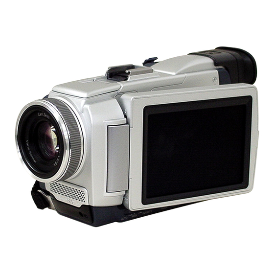
DCR-TRV40/TRV40E/
Photo: DCR-TRV50E
BLOCK DIAGRAMS
BLOCK DIAGRAMS
FRAME SCHEMATIC DIAGRAMS
SCHEMATIC DIAGRAMS
SCHEMATIC DIAGRAMS
Mounted parts location ............................. Pages 4-98 to 4-99
Electrical parts list ................................... Pages 6-18 to 6-25
DIGITAL VIDEO CAMERA RECORDER
TRV50/TRV50E
RMT-811
LEVEL
US Model
Canadian Model
AEP Model
East European Model
DCR-TRV40E/TRV50E
UK Model
Australian Model
DCR-TRV40/TRV40E/TRV50/TRV50E
Hong Kong Model
DCR-TRV40/TRV50E
Tourist Model
DCR-TRV40/TRV40E
Korea Model
Chinese Model
PRINTED WIRING BOARDS
ADJUSTMENTS
ADJUSTMENTS
REPAIR PARTS LIST
REPAIR PARTS LIST
2
DCR-TRV50
DCR-TRV50E
E Model
DCR-TRV40
DCR-TRV40E

Advertisement

Table of Contents
loading

Summary of Contents for Sony DCR-TRV40

  • Page 1 DCR-TRV40/TRV40E/ TRV50/TRV50E RMT-811 SERVICE MANUAL LEVEL US Model Canadian Model Ver 1.3 2003. 11 DCR-TRV50 AEP Model Revision History Revision History East European Model DCR-TRV40E/TRV50E UK Model Australian Model DCR-TRV50E E Model DCR-TRV40/TRV40E/TRV50/TRV50E Hong Kong Model DCR-TRV40/TRV50E Tourist Model DCR-TRV40/TRV40E...
  • Page 2 CRITIQUES POUR LA SÉCURITÉ DE FONCTIONNEMENT. NE COMPONENTS WITH SONY PARTS WHOSE PART NUMBERS REMPLACER CES COMPOSANTS QUE PAR DES PIÈSES SONY APPEAR AS SHOWN IN THIS MANUAL OR IN SUPPLEMENTS DONT LES NUMÉROS SONT DONNÉS DANS CE MANUEL OU PUBLISHED BY SONY.
  • Page 3 DCR-TRV40/TRV40E/TRV50/TRV50E • SUPPLIED ACCESSORIES Make sure that the following accessories are supplied with your camcorder. 1 AC-L10A/L10B/L10C AC power adaptor (1), qa CD-ROM (USB Driver) (1) mains lead (1) SPVD-008 (Except US, Canadian model only) 2 NP-FM50 battery pack (1)
  • Page 4: Table Of Contents

    DCR-TRV40/TRV40E/TRV50/TRV50E TABLE OF CONTENTS SERVICE NOTE FRAME SCHEMATIC DIAGRAM (3/4) ······················· 4-5 FRAME SCHEMATIC DIAGRAM (4/4) ······················· 4-7 1-1. SERVICE NOTE ····························································· 1-1 4-2. SCHEMATIC DIAGRAMS ·········································· 4-11 POWER SUPPLY DURING REPAIRS ·························· 1-1 • CD-381 (CCD IMAGER) HOW TO OPEN THE FLASH WHEN THE FLASH SCHEMATIC DIAGRAM ····························...
  • Page 5 DCR-TRV40/TRV40E/TRV50/TRV50E 4-5. MOUNTED PARTS LOCATION ································· 4-96 AF Laser Check ····························································· 5-35 Steady Shot Check ························································· 5-36 1-4. COLOR ELECTRONIC VIEWFINDER SYSTEM Mounted parts location of the VC-283 board is not shown. ADJUSTMENT ····························································· 5-37 Pages from 4-98 to 4-99 are not shown.
  • Page 6 DCR-TRV40/TRV40E/TRV50/TRV50E 4-3. SERVICE MODE ·························································· 5-62 Setting the Test Mode ···················································· 5-62 Emergence Memory Address ········································ 5-62 2-1. EMG Code (Emergency Code) ····································· 5-62 2-2. MSW Code ···································································· 5-63 Bit value discrimination ················································ 5-64 Switch check (1) ···························································· 5-64 Switch check (2) ···························································· 5-64 Switch check (3) ····························································...
  • Page 7: Service Note

    DCR-TRV40/TRV40E/TRV50/TRV50E SECTION 1 COVER COVER SERVICE NOTE 1-1. SERVICE NOTE POWER SUPPLY DURING REPAIRS In this unit, about 10 seconds after power is supplied to the battery terminal using the regulated power supply (8.4V), the power is shut off so that the unit cannot operate.
  • Page 8: Discharging Of The Flashlight Power

    DCR-TRV40/TRV40E/TRV50/TRV50E DISCHARGING OF THE FLASHLIGHT POWER SUPPLY CAPACITOR The power supply capacitor of the flash unit is charged up to the maximum 300V potential. There is a danger of electric shock by this high voltage when the capacitor is handled by hand. The electric shock is caused by the charged voltage which is kept without discharging when the main power of the unit is simply turned off.
  • Page 9: Self-Diagnosis Function

    DCR-TRV40/TRV40E/TRV50/TRV50E 1-2. SELF-DIAGNOSIS FUNCTION SELF-DIAGNOSIS FUNCTION SELF-DIAGNOSIS DISPLAY When problems occur while the unit is operating, the counter of the When problems occur while the unit is operating, the self-diagnosis viewfinder, LCD screen or LCD window consists of an alphabet function starts working, and displays on the viewfinder, LCD screen and 4-digit numbers, which blinks at 3.2 Hz.
  • Page 10: Self-Diagnosis Code Table

    DCR-TRV40/TRV40E/TRV50/TRV50E Ver 1.3 2003. 11 SELF-DIAGNOSIS CODE TABLE Self-diagnosis Code Block Detailed Symptom/State Correction Function Code Non-standard battery is used. Use the info LITHIUM battery. Condensation. Remove the cassette, and insert it again after one hour. Video head is dirty.
  • Page 11: Disassemly

    DCR-TRV40/TRV40E/TRV50/TRV50E SECTION 2 COVER COVER DISASSEMBLY The following flow chart shows the disassembly procedure. 2-1. LCD section (PD-165 board) (page 2-3) PD-165 board service position (page 2-3) 2-2. EVF section (LB-078 board) (page 2-4) LB-078 board service position (page 2-5) 2-3.
  • Page 12 DCR-TRV40/TRV40E/TRV50/TRV50E [CONNECTION OF EQUIPMENT] Screw (M1.7 × 4), CPC lid lock ace, p2 Adjustment remote commander (RM-95) CPC-7 jig AC power AC IN adaptor (J-6082-382-A)
  • Page 13: Lcd Section (Pd-165 Board)

    DCR-TRV40/TRV40E/TRV50/TRV50E NOTE: Follow the disassembly procedure in the numerical order given. 2-1. LCD SECTION (PD-165 BOARD) Five claws Two screws (M1.7 × 4), lock ace, p2 1 Two screws 4 P cabinet (c) assembly (M1.7 × 4), lock ace, p2...
  • Page 14: Evf Section (Lb-078 Board)

    DCR-TRV40/TRV40E/TRV50/TRV50E 2-2. EVF SECTION (LB-078 BOARD) 1 Raise the EVF in the direction of the arrow A and slide it in the direction of the arrow B . 2 Two tapping screws (M1.7 × 6) Caution When separating the 7 LB-078 board and...
  • Page 15: Top Cabinet

    DCR-TRV40/TRV40E/TRV50/TRV50E [LB-078 BOARD SERVICE POSITION] CPC-7 jig (J-6082-382-A) Adjustment remote commander (RM-95) LB-078 board VF lens assembly AC power AC IN adaptor 2-3. TOP CABINET 1 Screw (M1.7 × 4), lock ace, p2 4 Top cabinet 3 Claw 2 Screw (M1.7 × 4),...
  • Page 16: Front Panel Section

    DCR-TRV40/TRV40E/TRV50/TRV50E 2-4. FRONT PANEL SECTION Open the Flash unit by pushing the portion A . Two screws (M1.7 × 4), lock ace, p2 3 Open the jack cover assembly 4 Screw (M1.7 × 4), 7 JK-219 board (37P) lock ace, p2...
  • Page 17: Board

    DCR-TRV40/TRV40E/TRV50/TRV50E 2-5. MA-408 BOARD 2 Groove 5 Microphone unit (4P) 6 MA-408 board 4 SE-124 board (8P) 1 Screw (M1.7 × 2.5), lock ace, p2 3 Screw (M1.7 × 2.5), lock ace, p2 CPC-7 jig (J-6082-382-A) [MA-408 BOARD SERVICE POSITION]...
  • Page 18: Cabinet (R) Section (1)

    DCR-TRV40/TRV40E/TRV50/TRV50E 2-6. CABINET (R) SECTION (1) 2 Screw (M1.7 × 2.5), lock ace, p2 1 Screw (M1.7 × 2.5), lock ace, p2 2-7. CABINET (R) SECTION (2) Caution Because the 8 Cabinet (R) section is connected to the main unit using the 7 FP-456 flexible board, the flexible board may be damaged if you remove the Cabinet (R) section forcibly.
  • Page 19: Battery Section

    DCR-TRV40/TRV40E/TRV50/TRV50E 2-8. BATTERY SECTION 3 BT panel assembly 4 Open the cassette lid 1 Screw (M1.7 × 4), lock ace, p2 2 Strap bracket (lower) 4 Battery terminal board 7 BT panel section 3 Two screws (M1.7 × 4), lock ace, p2...
  • Page 20: External Connector (Hot Shoe)

    DCR-TRV40/TRV40E/TRV50/TRV50E 2-10.EXTERNAL CONNECTOR (HOT SHOE) 2 Two screws 5 Remove the External connector (M1.7 × 2.5), (hot shoe) and Shoe base lock ace, p2 in the direction of the arrow 6 FP-459 flexible board (15P) 1 Slide the EVF in the direction of the arrow A .
  • Page 21: Evf Section

    DCR-TRV40/TRV40E/TRV50/TRV50E 2-12.EVF SECTION 4 EVF section 1 Two tapping screws (M1.7 × 5) 2 FP-458 flexible board (21P) 3 Remove the EVF section from the groove. 2-13.FLASH UNIT (FLASH SECTION) (1) 3 Remove the Grip cover in the direction of the arrow.
  • Page 22 DCR-TRV40/TRV40E/TRV50/TRV50E 2-14.FLASH UNIT (FLASH SECTION) (2) 4 Remove the ST cover in the direction of the arrow. 3 Claw 1 From the flash unit (33P) 5 Tapping screw (M1.7 × 5) 2 Dowel 2-15.FLASH UNIT (FLASH SECTION) (3) 4 Flash unit...
  • Page 23: Flash Unit (Flash Section) (2)

    DCR-TRV40/TRV40E/TRV50/TRV50E 2-16.FLASH UNIT (FLASH SECTION) (4) Flash unit Caution Hinge assembly 6 Screw (M1.7 × 2.5), lock ace, p2 To install the Flash unit into the Hinge assembly, set the switch position as shown in the illustration. 0 ST hinge assembly...
  • Page 24 DCR-TRV40/TRV40E/TRV50/TRV50E 2-17.DD-176 BOARD 5 Board to board connector (100P) 3 Zoom cover 2 FP-459 flexible board (20P) 6 DD-176 board 1 From the flash unit (33P) 7 VC heat sink, VC radiation sheet B, VC insulating sheet 4 Two screws (M1.7 ×...
  • Page 25 DCR-TRV40/TRV40E/TRV50/TRV50E 2-18.VC-283 BOARD, MECHANISM DECK (1) From the Control switch block (FK-2890)(27P) From the Lens device (27P) From the CD-381 board (40P) From the JK-219 board (80P) 2-19.VC-283 BOARD, MECHANISM DECK (2) 2 Five dowels MD frame assembly VC-283 board...
  • Page 26: Flash Unit (Flash Section) (3)

    DCR-TRV40/TRV40E/TRV50/TRV50E 2-20.VC-283 BOARD, MECHANISM DECK (3) 1 Two screws 3 Remove the VC-283 board (M1.7 × 2.5), in the direction of the arrow. lock ace, p2 7 Mechanism deck, VC-283 board 2 Two grooves 5 Three dowels 6 MD frame assembly,...
  • Page 27 DCR-TRV40/TRV40E/TRV50/TRV50E 2-22.JK-219 BOARD 1 Screw (M1.7 × 2.5), lock ace, p2 3 Claw 2 Screw (M1.7 × 2.5), lock ace, p2 5 Two screws 4 Screw (M1.7 × 2.5), (M1.7 × 2.5), lock ace, p2 lock ace, p2 6 JK-219 board 2-23.CD-381 BOARD, 690C (CZ) BLOCK ASSEMBLY (LENS DEVICE)
  • Page 28 DCR-TRV40/TRV40E/TRV50/TRV50E [SERVICE POSITION TO CHECK THE VTR SECTION] Connection to Check the VTR Section To check the VTR section, set the VTR to the “Forced VTR power ON” mode. Operate the VTR functions using the adjustment remote commander (with the HOLD switch set in the OFF position).
  • Page 29: Lens Section

    DCR-TRV40/TRV40E/TRV50/TRV50E [SERVICE POSITION TO CHECK THE CAMERA SECTION] Connection to Check the Camera Section To check the CAMERA section, set the CAMERA to the “Forced camera power ON” mode. When you want to operate the ZOOM and FOCUS, use the controls on the remote commander (with HOLD switch off).
  • Page 30: Cs Frame Assembly

    DCR-TRV40/TRV40E/TRV50/TRV50E 2-24.CS FRAME ASSEMBLY (Before starting disassembling, remove the glip cover and discharge the power supply capacitor referring to section 2-13) 5 Four dowels 1 FP-460 flexible board (15P) 3 Two tapping screws (M1.7 × 5) 2 Three tapping screws (M1.7 ×...
  • Page 31: Control Switch Block (Ps-2890)

    DCR-TRV40/TRV40E/TRV50/TRV50E 2-26.CONTROL SWITCH BLOCK (PS-2890) 2 Control switch block (PS-2890)(8P) 3 Control switch block (PS-2890) 1 Tapping screw (M1.7 × 5) 2-27.MEMORY STICK CONNECTOR Caution When removing the 3 Grip block assembly, be careful that it can be easily caught by the dowel and the protrusion of the Eject knob shown in the illustration.
  • Page 32: Board, Speaker (2.0Cm)

    DCR-TRV40/TRV40E/TRV50/TRV50E 2-28.CK-115 BOARD, SPEAKER (2.0CM) qd Speaker (2.0cm) 7 Control switch block qs Speaker retainer assembly (KY-2890)(10P) qa Two tapping screws (M1.7 × 3.5) 4 Two claws 8 Speaker (2P) 0 SP insulating sheet 6 Control switch block (KP-2890)(8P) 1 FP-461 flexible board (6P)
  • Page 33: Hinge Assembly

    DCR-TRV40/TRV40E/TRV50/TRV50E 2-30.HINGE ASSEMBLY 6 Hinge cover (rear) 4 Two claws 8 FP-461 flexible board (6P) 7 Screw (M1.7 × 2.5), lock ace, p2 2 Screw (M1.7 × 4), lock ace, p2 1 Rotate the Hinge assembly in the direction of the arrow...
  • Page 34: Circuit Boards Location

    DCR-TRV40/TRV40E/TRV50/TRV50E 2-31.CIRCUIT BOARDS LOCATION LB-078 VC-283 CD-381 JK-219 DD-176 BT-003 MA-408 SE-124 CK-115 INVERTER PD-165 TRANSFORMER UNIT NAME FUNCTION BLUE TOOTH (Schematic diagram and printed wiring board to replace blocks are not listed.) BT-003 CD-381 CCD IMAGER CK-115 CONTROL SWITCH...
  • Page 35: Flexible Boards Location

    DCR-TRV40/TRV40E/TRV50/TRV50E 2-32.FLEXIBLE BOARDS LOCATION The flexible boards contained in the mechanism deck are not shown. CONTROL SWITCH BLOCK CONTROL SWITCH BLOCK (FK-2890) (KY-2890) FP-461 FP-456 FP-457 (TRV50/TRV50E) FP-459 FLASH UNIT CONTROL SWITCH BLOCK (KP-2890) CONTROL SWITCH BLOCK (PS-2890) FP-460 FP-458...
  • Page 36: Block Diagrams

    DCR-TRV40/TRV40E/TRV50/TRV50E COVER COVER 3. BLOCK DIAGRAMS Link Link OVERALL BLOCK DIAGRAM (1/4) POWER BLOCK DIAGRAM (1/2) OVERALL BLOCK DIAGRAM (1/4) POWER BLOCK DIAGRAM (1/2) OVERALL BLOCK DIAGRAM (2/4) POWER BLOCK DIAGRAM (2/2) OVERALL BLOCK DIAGRAM (2/4) POWER BLOCK DIAGRAM (2/2)
  • Page 37 DCR-TRV40/TRV40E/TRV50/TRV50E SECTION 3 3. BLOCK DIAGRAMS 3. BLOCK DIAGRAMS COVER COVER BLOCK DIAGRAMS 3-1. OVERALL BLOCK DIAGRAM (1/4) ( ) : Number in parenthesis ( ) indicates the division number of schematic diagram where the component is located. LENS ASSY...
  • Page 38 DCR-TRV40/TRV40E/TRV50/TRV50E 3. BLOCK DIAGRAMS 3. BLOCK DIAGRAMS COVER COVER ( ) : Number in parenthesis ( ) indicates the division number of schematic diagram where the component is located. 3-2. OVERALL BLOCK DIAGRAM (2/4) PD-165 BOARD(1/2) CN1005 CN5201 CN5206 CN5806...
  • Page 39 DCR-TRV40/TRV40E/TRV50/TRV50E 3. BLOCK DIAGRAMS 3. BLOCK DIAGRAMS COVER COVER 3-3. OVERALL BLOCK DIAGRAM (3/4) ( ) : Number in parenthesis ( ) indicates the division number of schematic diagram where the component is located. CN1012 J MECHA DECK FOR ADJUSTMENTS...
  • Page 40 DCR-TRV40/TRV40E/TRV50/TRV50E 3. BLOCK DIAGRAMS 3. BLOCK DIAGRAMS COVER COVER ( ) : Number in parenthesis ( ) indicates the division number of schematic diagram where the component is located. 3-4. OVERALL BLOCK DIAGRAM (4/4) CK-115 CK-115 BOARD (2/3) VC-283 BOARD(5/5)
  • Page 41 DCR-TRV40/TRV40E/TRV50/TRV50E 3. BLOCK DIAGRAMS 3. BLOCK DIAGRAMS COVER COVER 3-5. POWER BLOCK DIAGRAM (1/2) ( ) : Number in parenthesis ( ) indicates the division number of schematic diagram where the component is located. DD-176 BOARD VC-283 BOARD (1/2) CN4604...
  • Page 42 DCR-TRV40/TRV40E/TRV50/TRV50E 3. BLOCK DIAGRAMS 3. BLOCK DIAGRAMS COVER COVER ( ) : Number in parenthesis ( ) indicates the division number of schematic diagram where the component is located. 3-6. POWER BLOCK DIAGRAM (2/2) (DCR-TRV50/TRV50E) VC-283 BOARD(2/2) BLUE TOOTH PANEL 4.6V...
  • Page 43: Printed Wiring Boards And Schematic Diagrams

    DCR-TRV40/TRV40E/TRV50/TRV50E 4-2. SCHEMATIC DIAGRAMS 4-2. SCHEMATIC DIAGRAMS 4-3. PRINTED WIRING BOARDS 4-3. PRINTED WIRING BOARDS COVER COVER SECTION 4 PRINTED WIRING BOARDS AND SCHEMATIC DIAGRAMS 4-1. FRAME SCHEMATIC DIAGRAM (1/4) (TRV50/TRV50E) CONTROL CN101 CN1004 SWITCH FP-461 REG_GND REG_GND SP901 SPEAKER...
  • Page 44: Frame Schematic Diagram (1/4)

    DCR-TRV40/TRV40E/TRV50/TRV50E 4-2. SCHEMATIC DIAGRAMS 4-2. SCHEMATIC DIAGRAMS 4-3. PRINTED WIRING BOARDS 4-3. PRINTED WIRING BOARDS COVER COVER FRAME SCHEMATIC DIAGRAM (2/4) CN5303 80P CN1006 MIC901 N.C. XF_TALLY_LED CN5903 MIC UNIT XF_TALLY_LED MF_LED MF_A CN5901 INT_MIC_L MF_LED MF_B LANC_DC INT_MIC_GND MF_A...
  • Page 45: Frame Schematic Diagram (2/4)

    DCR-TRV40/TRV40E/TRV50/TRV50E 4-2. SCHEMATIC DIAGRAMS 4-2. SCHEMATIC DIAGRAMS 4-3. PRINTED WIRING BOARDS 4-3. PRINTED WIRING BOARDS COVER COVER FRAME SCHEMATIC DIAGRAM (3/4) CONTROL SWITCH CN3211 BLOCK(PS-2890) BL_GND ND901 S/S SW BACK LIGHT VTR/CAM/PHOTO BL_LOW EJECT_SW N.C. N.C. N.C. N.C. 3.5INCH LCD UNIT N.C.
  • Page 46: Frame Schematic Diagram (3/4)

    DCR-TRV40/TRV40E/TRV50/TRV50E 4-2. SCHEMATIC DIAGRAMS 4-2. SCHEMATIC DIAGRAMS 4-3. PRINTED WIRING BOARDS 4-3. PRINTED WIRING BOARDS COVER COVER FRAME SCHEMATIC DIAGRAM (4/4) XENON LAMP INTELLIGENT ACCESSORY SHOE CN4607 XE_A XE_A CN1003 B TO B CN4601 XE_A 100P 100P DRUM_VS MT_4.9V XE_A DRUM_VS MT_4.9V...
  • Page 47 DCR-TRV40/TRV40E/TRV50/TRV50E 4-2. SCHEMATIC DIAGRAMS 4-2. SCHEMATIC DIAGRAMS 4-3. PRINTED WIRING BOARDS 4-3. PRINTED WIRING BOARDS COVER COVER THIS NOTE IS COMMON FOR WIRING BOARDS AND SCHEMATIC DIAGRAMS (In addition to this, the necessary note is printed in each block) (Measuring conditions voltage and waveform) (For printed wiring boards) •...
  • Page 48: Schematic Diagrams

    DCR-TRV40/TRV40E/TRV50/TRV50E COVER COVER 4-2. SCHEMATIC DIAGRAMS Link Link CD-381 BOARD CD-381 BOARD (CCD IMAGER) (CCD IMAGER) JK-219 BOARD JK-219 BOARD (AV IN/OUT, STEADY SHOT) (AV IN/OUT, STEADY SHOT) CK-115 BOARD CK-115 BOARD (CONTROL SWITCH) (CONTROL SWITCH) FK-2890, PS-2890 FK-2890, PS-2890...
  • Page 49 DCR-TRV40/TRV40E/TRV50/TRV50E 4-2. SCHEMATIC DIAGRAMS 4-2. SCHEMATIC DIAGRAMS CD-381 PRINTED WIRING BOARD CD-381 PRINTED WIRING BOARD COVER COVER For Schematic Diagram 4-2. SCHEMATIC DIAGRAMS • Refer to page 4-71 for printed wiring board. • Refer to page 4-93 for waveforms. CD-381 BOARD...
  • Page 50: Av In/Out,Steady Shot

    DCR-TRV40/TRV40E/TRV50/TRV50E 4-2. SCHEMATIC DIAGRAMS 4-2. SCHEMATIC DIAGRAMS JK-219 BOARD SIDE A JK-219 BOARD SIDE A JK-219 BOARD SIDE B JK-219 BOARD SIDE B COVER COVER For Schematic Diagram • Refer to page 4-73 for printed wiring board. JK-219 BOARD NO MARK:REC/PB MODE...
  • Page 51: Control Switch

    DCR-TRV40/TRV40E/TRV50/TRV50E 4-2. SCHEMATIC DIAGRAMS 4-2. SCHEMATIC DIAGRAMS CK-115 PRINTED WIRING BOARD CK-115 PRINTED WIRING BOARD COVER COVER For Schematic Diagram • Refer to page 4-77 for printed wiring board. CN5205 CK-115 BOARD SP901 CONTROL SWITCH (SPEAKER) XX MARK:NO MOUNT R5203...
  • Page 52: Flexible

    DCR-TRV40/TRV40E/TRV50/TRV50E 4-2. SCHEMATIC DIAGRAMS 4-2. SCHEMATIC DIAGRAMS 4-3. PRINTED WIRING BOARDS 4-3. PRINTED WIRING BOARDS COVER COVER CONTROL SWITCH BLOCK CONTROL SWITCH BLOCK (FK-2890) (PS-2890) D001 POWER CN001 (DCR-TRV50/ XMS_ACCESS TRV50E) MS_ACCESS S004 MS_LED_VCC MEMORY/NETWORK XPHOTO_STBY_SW S002 XCAM_STBY_SW CAMERA OFF(CHG)
  • Page 53: 1/2)

    DCR-TRV40/TRV40E/TRV50/TRV50E 4-2. SCHEMATIC DIAGRAMS 4-2. SCHEMATIC DIAGRAMS MA-408 PRINTED WIRING BOARD MA-408 PRINTED WIRING BOARD COVER COVER For Schematic Diagram • Refer to page 4-79 for printed wiring board. MA-408 BOARD(1/2) MIC AMP,REMOTE COMMANDER RECEIVER XX MARK:NO MOUNT EXT_IN_L C5935 C5937 0.1u...
  • Page 54: 2/2)(Lanc, Ext Mic)

    DCR-TRV40/TRV40E/TRV50/TRV50E 4-2. SCHEMATIC DIAGRAMS 4-2. SCHEMATIC DIAGRAMS MA-408 PRINTED WIRING BOARD MA-408 PRINTED WIRING BOARD COVER COVER For Schematic Diagram • Refer to page 4-79 for printed wiring board. MA-408 BOARD(2/2) LANC,EXT MIC XX MARK:NO MOUNT SE-124 BOARD MF_LED NO MARK:REC/PB MODE...
  • Page 55 DCR-TRV40/TRV40E/TRV50/TRV50E 4-2. SCHEMATIC DIAGRAMS 4-2. SCHEMATIC DIAGRAMS PD-165 PRINTED WIRING BOARD PD-165 PRINTED WIRING BOARD COVER COVER For Schematic Diagram • Refer to page 4-83 for printed wiring board. • Refer to page 4-93 for waveforms. PD-165 BOARD(1/2) NO MARK:REC/PB MODE...
  • Page 56 DCR-TRV40/TRV40E/TRV50/TRV50E 4-2. SCHEMATIC DIAGRAMS 4-2. SCHEMATIC DIAGRAMS PD-165 PRINTED WIRING BOARD PD-165 PRINTED WIRING BOARD COVER COVER For Schematic Diagram • Refer to page 4-83 for printed wiring board. • Refer to page 4-93 for waveforms. PD-165 BOARD(2/2) LCD DRIVER,BACKLIGHT...
  • Page 57 DCR-TRV40/TRV40E/TRV50/TRV50E 4-2. SCHEMATIC DIAGRAMS 4-2. SCHEMATIC DIAGRAMS DD-1176 PRINTED WIRING BOARD DD-1176 PRINTED WIRING BOARD COVER COVER For Schematic Diagram • Refer to page 4-85 for printed wiring board. DD-176 BOARD(1/2) BATT/XEXT DC/DC CONVERTER BATT_SIG XX MARK:NO MOUNT D4501 FAST_CHARGE...
  • Page 58 DCR-TRV40/TRV40E/TRV50/TRV50E 4-2. SCHEMATIC DIAGRAMS 4-2. SCHEMATIC DIAGRAMS DD-176 BOARD DD-176 BOARD LB-078 BOARD LB-078 BOARD COVER COVER For Schematic Diagram • Refer to page 4-85 for printed wiring board. DD-176 BOARD(2/2) CONNECTOR CN4601 100P B TO B XX MARK:NO MOUNT DRUM_VS MT_4.9V...
  • Page 59 DCR-TRV40/TRV40E/TRV50/TRV50E 4-2. SCHEMATIC DIAGRAMS 4-2. SCHEMATIC DIAGRAMS FP-100, FP-228, FP-102 FLEXIBLE BOARD FP-100, FP-228, FP-102 FLEXIBLE BOARD COVER COVER For Schematic Diagram • Refer to page 4-87 for printed wiring board. (PAGE 4-60) TO VC-283 BOARD(14/19) CN1010 FP-228 LM_LOAD FLEXIBLE...
  • Page 60 Schematic diagram of the VC-283 board are not shown. Pages from 4-33 to 4-70 are not shown.
  • Page 61: Flexible Board

    DCR-TRV40/TRV40E/TRV50/TRV50E COVER COVER 4-3. PRINTED WIRING BOARDS Link Link CD-381 BOARD CD-381 BOARD SE-124 BOARD SE-124 BOARD FP-460 FLEXIBLE BOARD PD-165 BOARD FP-460 FLEXIBLE BOARD PD-165 BOARD JK-219 BOARD (SIDE A) DD-176 BOARD JK-219 BOARD (SIDE A) DD-176 BOARD JK-219 BOARD (SIDE B)
  • Page 62: Ccd Imager)

    DCR-TRV40/TRV40E/TRV50/TRV50E MOUNTED PARTS LOCATION 4-2. SCHEMATIC DIAGRAMS 4-2. SCHEMATIC DIAGRAMS 4-3. PRINTED WIRING BOARDS 4-3. PRINTED WIRING BOARDS MOUNTED PARTS LOCATION COVER COVER 4-3. PRINTED WIRING BOARDS • : Uses unleaded solder. CD-381 (CCD IMAGER) PRINTED WIRING BOARD FP-460 FLEXIBLE BOARD...
  • Page 63 DCR-TRV40/TRV40E/TRV50/TRV50E MOUNTED PARTS LOCATION 4-2. SCHEMATIC DIAGRAMS 4-2. SCHEMATIC DIAGRAMS 4-3. PRINTED WIRING BOARDS 4-3. PRINTED WIRING BOARDS MOUNTED PARTS LOCATION COVER COVER JK-219 (AV IN/OUT, STEADY SHOT) PRINTED WIRING BOARD • : Uses unleaded solder. S VIDEO DV IN/OUT...
  • Page 64 DCR-TRV40/TRV40E/TRV50/TRV50E MOUNTED PARTS LOCATION 4-2. SCHEMATIC DIAGRAMS 4-2. SCHEMATIC DIAGRAMS 4-3. PRINTED WIRING BOARDS 4-3. PRINTED WIRING BOARDS MOUNTED PARTS LOCATION COVER COVER • : Uses unleaded solder. (FLASH) JK-219 4-75 4-76...
  • Page 65: Control Switch)

    DCR-TRV40/TRV40E/TRV50/TRV50E MOUNTED PARTS LOCATION 4-2. SCHEMATIC DIAGRAMS 4-2. SCHEMATIC DIAGRAMS 4-3. PRINTED WIRING BOARDS 4-3. PRINTED WIRING BOARDS MOUNTED PARTS LOCATION COVER COVER CK-115 (CONTROL SWITCH) PRINTED WIRING BOARD • : Uses unleaded solder. CAUTION : Danger of explosion if battery is incorrectly replaced.
  • Page 66: Mic Amp, Remote Commander Receiver, Lanc, Ext Mic) Printed Wiring Board

    DCR-TRV40/TRV40E/TRV50/TRV50E MOUNTED PARTS LOCATION 4-2. SCHEMATIC DIAGRAMS 4-2. SCHEMATIC DIAGRAMS 4-3. PRINTED WIRING BOARDS 4-3. PRINTED WIRING BOARDS MOUNTED PARTS LOCATION COVER COVER MA-408 (MIC AMP, REMOTE COMMANDER RECEIVER, LANC, EXT MIC) PRINTED WIRING BOARD • : Uses unleaded solder.
  • Page 67: Flexible Board

    DCR-TRV40/TRV40E/TRV50/TRV50E 4-2. SCHEMATIC DIAGRAMS 4-2. SCHEMATIC DIAGRAMS 4-3. PRINTED WIRING BOARDS 4-3. PRINTED WIRING BOARDS COVER COVER FP-461 FLEXIBLE BOARD SE-124 (MF SENSOR) PRINTED WIRING BOARD • : Uses unleaded solder. • : Uses unleaded solder. FP-461 FLEXIBLE For printed wiring boards •...
  • Page 68 DCR-TRV40/TRV40E/TRV50/TRV50E MOUNTED PARTS LOCATION 4-2. SCHEMATIC DIAGRAMS 4-2. SCHEMATIC DIAGRAMS 4-3. PRINTED WIRING BOARDS 4-3. PRINTED WIRING BOARDS MOUNTED PARTS LOCATION COVER COVER PD-165 (RGB DRIVE, TIMING GENERATOR, LCD DRIVER, BACK LIGHT) PRINTED WIRING BOARD • : Uses unleaded solder.
  • Page 69 DCR-TRV40/TRV40E/TRV50/TRV50E MOUNTED PARTS LOCATION 4-2. SCHEMATIC DIAGRAMS 4-2. SCHEMATIC DIAGRAMS 4-3. PRINTED WIRING BOARDS 4-3. PRINTED WIRING BOARDS MOUNTED PARTS LOCATION COVER COVER DD-176 (DC/DC CONVERTER, CONNECTOR) PRINTED WIRING BOARD • : Uses unleaded solder. For printed wiring boards • Refer to page 4-97 for parts location.
  • Page 70: Printed Wiring Board

    DCR-TRV40/TRV40E/TRV50/TRV50E 4-2. SCHEMATIC DIAGRAMS 4-2. SCHEMATIC DIAGRAMS 4-3. PRINTED WIRING BOARDS 4-3. PRINTED WIRING BOARDS COVER COVER Printed wiring board of the VC-283 board are not shown. Pages from 4-89 to 4-92 are not shown. FP-100 (MODE SWITCH), FP-228 (DEW SENSOR), FP-102 (TAPE TOP/END SENSOR, S/T REEL) FLEXIBLE BOARDS •...
  • Page 71: Waveforms

    DCR-TRV40/TRV40E/TRV50/TRV50E CD-381 BOARD CD-381 BOARD PD-165 BOARD PD-165 BOARD COVER COVER 4-4. WAVEFORMS CD-381 PD-165 BOARD BOARD IC7301 1,4 IC5701 rh IC5702 rk CAMERA REC 7.7 Vp-p 3.0Vp-p 550mVp-p 44.4 µsec IC7301 2,3 IC5701 rj IC5702 1 CAMERA REC 7.7 Vp-p 44.4 µsec...
  • Page 72: Mounted Parts Location

    DCR-TRV40/TRV40E/TRV50/TRV50E 4-3. PRINTED WIRING BOARDS 4-3. PRINTED WIRING BOARDS COVER COVER 4-5. MOUNTED PARTS LOCATION no mark : side A * mark : side B CD-381 BOARD JK-219 BOARD CK-115 BOARD MA-408 BOARD * C7302 * C5351 R5301 E-4 * BT5201 A-1...
  • Page 73 DCR-TRV40/TRV40E/TRV50/TRV50E 4-3. PRINTED WIRING BOARDS 4-3. PRINTED WIRING BOARDS COVER COVER no mark : side A * mark : side B PD-165 BOARD DD-176 BOARD C5701 IC5701 C-4 * C4501 F4504 * R4530 B-1 C5702 IC5702 B-2 * C4503 F4505...
  • Page 74: Pages From 4-98 To 4-99 Are Not Shown

    Mounted parts location of the VC-283 board is not shown. Pages from 4-98 to 4-99 are not shown.
  • Page 75 DCR-TRV40/TRV40E/TRV50/TRV50E SECTION 5 COVER COVER ADJUSTMENTS...
  • Page 76: Adjustment

    DCR-TRV40/TRV40E/TRV50/TRV50E 1. Adjusting items when replacing main parts and boards. • Adjusting items when replacing main parts When replacing main parts, adjust the items indicated by in the following table. Note: When replacing the drum assembly or the mechanism deck, reset the data of page: 7, address: A7 to A9 to “00”. (Refer to “Record of Use check” of “5- 4.
  • Page 77 DCR-TRV40/TRV40E/TRV50/TRV50E • Adjusting items when replacing a board or EEPROM When replacing a board or EFPROM, adjust the items indicated by in the following table. Note2: When the repair is finished, confirm the EEPROM Board replacement following items. replacement Shoot the all black subject (Attach the...
  • Page 78: Camera Section Adjustment

    DCR-TRV40/TRV40E/TRV50/TRV50E 5-1. CAMERA SECTION ADJUSTMENT 1-1. PREPARATIONS BEFORE ADJUSTMENT (CAMERA SECTION) 1-1-1. List of Service Tools • Oscilloscope • Color monitor • Vectorscope • Regulated power supply • Digital voltmeter Ref. No. Name Parts Code Usage Filter for color temperature correction (C14)
  • Page 79: Preparations

    DCR-TRV40/TRV40E/TRV50/TRV50E 1-1-2. Preparations Note1: For details of how remove the cabinet and boards, refer to “2. Pattern box DISASSEMBLY”. Note2: When performing only the adjustments, the lens block and boards need not be disassembled. Note3: Before performing the adjustments, check the data of page: 0, address: 10 is “00”.
  • Page 80 DCR-TRV40/TRV40E/TRV50/TRV50E Color monitor Vector scope Adjustment remote commander VIDEO (Yellow) Terminated at 75 Ω AUDIO L (White) EVF block AUDIO R (Red) AUDIO/VIDEO jack Must be connected when using the flush unit. LANC jack Must be connected when performing the EVF system adjustment.
  • Page 81: Precaution

    DCR-TRV40/TRV40E/TRV50/TRV50E 1-1-3. Precaution 1. Setting the Switch Unless otherwise specified, set the switches as follows and perform adjustments without loading cassette. POWER switch (PS-2890 block) ......CAMERA 16 : 9 WIDE (Menu setting) ..........OFF NIGHT SHOT switch (Lens block) ......... OFF 10.
  • Page 82: Initialization Of 8, A, B, C, D, E, F, 1B, 1E, 1F

    DCR-TRV40/TRV40E/TRV50/TRV50E 1-2. INITIALIZATION OF 8, A, B, C, D, E, F, 1B, 1E, 1F PAGE DATA Note: When reading or writing the 1B, 1E or 1F page data, select page: 0, address: 10, and set data: 01, then select B, E or F page. The 1B, 1E or 1F page can be chosen by this data setting.
  • Page 83: Initialization Of A, D Page Data

    When changing the data, copy Note2: The power supply voltage must be 6.0 ± 0.1Vdc. the data built in the same model. Note3: NTSC model: DCR-TRV40/TRV50 Note: If copy the data built in the different model, the camcorder may PAL model: DCR-TRV40E/TRV50E not operate.
  • Page 84 DCR-TRV40/TRV40E/TRV50/TRV50E A page Address Address Remark Remark Address Initial value Initial value Remark Initial value Initial value NTSC PAL Fixed data-2 94 to C1 Fixed data-1 (Modified data. Copy the data Fixed data-2 built in the same model.) C3 to D3 Fixed data-1 Table.
  • Page 85: Modification Of B, 1B Page Data

    DCR-TRV40/TRV40E/TRV50/TRV50E 1-2-2. INITIALIZATION OF B, 1B PAGE DATA Processing after Completing Modification of B, 1B Page data: Order Page Address Data Procedure Note: When reading or writing the B page data, select page: 0, address: Set the data. 10, and set data: 00.
  • Page 86 DCR-TRV40/TRV40E/TRV50/TRV50E 5. B Page Table Note1: The data of page: 0, address: 10 must be “00”. Note2: Fixed data-1: Initialized data. (Refer to “1. Initializing the B, 1B Page Data”.) Fixed data-2: Modified data. (Refer to “2. Modification of B, 1B Page Data”).
  • Page 87: Page Table

    DCR-TRV40/TRV40E/TRV50/TRV50E 1-2-3. INITIALIZATION OF 8, C PAGE DATA 3. 8 Page Table Note: The data of page: 0, address: 10 must be “00”. Note1: The data of page: 0, address: 10 must be “00”. 1. Initializing the 8, C Page Data Note2: Fixed data-1: Initialized data.
  • Page 88 DCR-TRV40/TRV40E/TRV50/TRV50E 4. C Page Table Note1: The data of page: 0, address: 10 must be “00”. Address Initial value Initial value Remark Note2: Fixed data-1: Initialized data. (Refer to “1. Initializing the 8, C NTSC PAL Page Data”.) Fixed data-2: Modified data. (Refer to “2. Modification of 8, C RGB AMP adj.
  • Page 89 DCR-TRV40/TRV40E/TRV50/TRV50E C page Address Initial value Initial value Remark NTSC PAL Fixed data-2 Fixed data-1 Fixed data-2 (Modified data. Copy the data built in the same model.) DF to E1 Fixed data-1 Fixed data-2 E4 to E5 Fixed data-1 Fixed data-2...
  • Page 90 Note: If copy the data built in the different model, the camcorder may Note3: The power supply voltage must be 6.0 ± 0.1Vdc. not operate. Note4: NTSC model: DCR-TRV40/TRV50 5) When changing the data, press the PAUSE button of the PAL model: DCR-TRV40E/TRV50E adjustment remote commander each time when setting new data to write the data in the non-volatile memory.
  • Page 91 DCR-TRV40/TRV40E/TRV50/TRV50E 3. E Page Table Address Remark Note1: The data of page: 0, address: 10 must be “00”. Fixed data-2 Note2: Fixed data-1: Initialized data. (Refer to “1. Initializing the E, F, (Modified data. Copy the data 1E, 1F Page Data”.) Fixed data-2: Modified data.
  • Page 92 DCR-TRV40/TRV40E/TRV50/TRV50E 4. F Page Table Address Initial value Initial value Remark Note1: The data of page: 0, address: 10 must be “00”. NTSC PAL Note2: Fixed data-1: Initialized data. (Refer to “1. Initializing the E, F, Flange back adj. 1E, 1F Page Data”.) Fixed data-2: Modified data.
  • Page 93 DCR-TRV40/TRV40E/TRV50/TRV50E 5. 1E Page Table Address Initial value Initial value Remark Note1: When reading or writing the 1E page data, select page: 0, address: NTSC PAL 10, and set data: 01, then select E page. The 1E page can be chosen Strobe light level adjustment by this data setting.
  • Page 94 DCR-TRV40/TRV40E/TRV50/TRV50E 6. 1F Page Table Address Address Remark Remark Initial value Initial value Note1: When reading or writing the 1F page data, select page: 0, address: Fixed data-2 10, and set data: 01, then select F page. The 1F page can be chosen...
  • Page 95: Camera System Adjustments

    “VIDEO SYSTEM ADJUSTMENTS” are satisfied. And check that the data of page: 0, address: 10 is “00”. If not, set data: 00 to this address. Note: NTSC model: DCR-TRV40/TRV50 PAL model: DCR-TRV40E/TRV50E 1. 40.5MHz/54MHz Origin Oscillation Adjustment (VC-283 board) Set the frequency of the clock for synchronization.
  • Page 96: Hall Adjustment

    DCR-TRV40/TRV40E/TRV50/TRV50E 2. HALL Adjustment Processing after Completing Adjustments: Order Page Address Data Procedure For detecting the position of the lens iris and ND filter, adjust AMP Set the data. gain and offset. Set the data. Subject Not required Set the data, and press PAUSE...
  • Page 97: Max Gain Adjustment

    DCR-TRV40/TRV40E/TRV50/TRV50E 3. MAX GAIN Adjustment 4. CCD Output 2ch Matching Adjustment (1) Setting the minimum illumination. Correct the dispersion of the black level between the left-right If it is not consistent, the image level required for taking subjects in channels of the CCD imager.
  • Page 98: Ccd Output 2Ch Matching Adjustment (2)

    DCR-TRV40/TRV40E/TRV50/TRV50E 5. CCD Output 2ch Matching Adjustment (2) 6. MR Adjustment Correct the dispersion between the left-right channels of the CCD The MR (Magnet resistor) adjustment of the inner focus lens is imager. carried out automatically. In whichever case, the focus will be deviated during auto focusing/manual focusing.
  • Page 99 DCR-TRV40/TRV40E/TRV50/TRV50E 7. Flange Back Adjustment (Using Minipattern Box) Adjusting method: The inner focus lens flange back adjustment is carried out Order Page Address Data Procedure automatically. In whichever case, the focus will be deviated during Set the data. auto focusing/manual focusing.
  • Page 100: Flange Back Adjustment (Using Flange Back Adjustment Chart And Subject More Than 500M Away)

    DCR-TRV40/TRV40E/TRV50/TRV50E 8. Flange Back Adjustment 8-2. Flange Back Adjustment (2) (Using Flange Back Adjustment Chart and Subject Perform this adjustment after performing “Flange Back Adjustment More Than 500m Away) (1)”. The inner focus lens flange back adjustment is carried out...
  • Page 101: Flange Back Check

    DCR-TRV40/TRV40E/TRV50/TRV50E 9. Flange Back Check 10. Picture Frame Setting Subject Siemens star Subject Color bar chart (2.0m from the front of the lens) (Color reproduction adjustment frame) (Luminance : approx. 200 lux) (1.5m from the front of the lens) Measurement Point...
  • Page 102: Color Reproduction Adjustment

    All color luminance points should settle within each color reproduction For NTSC model frame. Note1: The data of page: 0, address: 10 must be “00”. Note2: NTSC model: DCR-TRV40/TRV50 PAL model: DCR-TRV40E/TRV50E Switch setting: 1) POWER ..............CAMERA 2) NIGHT SHOT ..............OFF 3) DIGITAL ZOOM (Menu display) ........
  • Page 103: Auto White Balance & Lv Standard Data Input

    DCR-TRV40/TRV40E/TRV50/TRV50E 12. Auto White Balance & LV Standard Data Input Adjust the white balance reference at 3200K, and adjust the normal coefficient of the light value. Subject Clear chart (Color reproduction adjustment frame) Measurement Point Display data of page 1 (Note5)
  • Page 104: Auto White Balance Adjustment

    DCR-TRV40/TRV40E/TRV50/TRV50E 13. Auto White Balance Adjustment Adjusting method: Adjust to the proper auto white balance output data. Order Page Address Data Procedure If it is not correct, auto white balance and color reproducibility will Place the C14 filter for color be poor.
  • Page 105: White Balance Check

    DCR-TRV40/TRV40E/TRV50/TRV50E 14. White Balance Check Subject Clear chart (Color reproduction adjustment frame) Filter Filter C14 for color temperature correction ND filter 1.0 and 0.4 and 0.1 Measurement Point Video output terminal Measuring Instrument Vectorscope Specified Value Fig. 5-1-13. A to B Note1: The data of page: 0, address: 10 must be “00”.
  • Page 106: Mechanical Shutter Adjustment

    DCR-TRV40/TRV40E/TRV50/TRV50E 15. Mechanical Shutter Adjustment 16. Black Defective CCD Adjustment Detect the black defective positions of the CCD imager. Adjustment Page Subject Clear chart (All white) Adjustment Address 76 to 8B (Approx. 40cm from the front of the lens) Note: The data of page: 0, address: 10 must be “00”.
  • Page 107: Strobe Light Level Adjustment

    DCR-TRV40/TRV40E/TRV50/TRV50E 17. Strobe Light Level Adjustment 18. Strobe White Balance Adjustment & Check Adjust the light level when the strobe light flashes. Adjust and check the white balance when the strobe light flashes. Subject Paper which reflection rate is 18%...
  • Page 108: Af Laser Output Adjustment

    DCR-TRV40/TRV40E/TRV50/TRV50E 19. AF Laser Output Adjustment Set the AF laser output to an appropriate level. Subject Paper which reflection rate is 18% (50cm from the front of the lens) (Note1) Measurement Point Adjustment remote commander Measuring Instrument Adjustment Page Adjustment Address...
  • Page 109: Af Laser Check

    DCR-TRV40/TRV40E/TRV50/TRV50E 20. AF Laser Check inspection frame Subject Paper which reflection rate is 18% (1m from the front of the lens) (Note1) Measurement Point Check operation on LCD screen Measuring Instrument Specified Value Two or more hologram lines are perfectly within the inspection frame.
  • Page 110: Steady Shot Check

    DCR-TRV40/TRV40E/TRV50/TRV50E 21. Steady Shot Check Precautions on the Parts Replacement There are two types of repair parts. Type A: ENC03LA Type B: ENC03LB Replace the broken sensor with a same type sensor. If replace with other type parts, the image will vibrate up and down or left and right during hand-shake correction operations.
  • Page 111: Color Electronic Viewfinder System

    1) Select page: 3, address: C4, and set data: 00. Note1: The data of page: 0, address: 10 must be “00”. 2) Select page: 3, address: C5, and set data: 00. Note4: NTSC model: DCR-TRV40/TRV50 PAL model: DCR-TRV40E/TRV50E Adjusting method:...
  • Page 112: Rgb Amp Adjustment (Vc-283 Board)

    DCR-TRV40/TRV40E/TRV50/TRV50E 2. RGB AMP Adjustment (VC-283 board) 3. Contrast Adjustment (VC-283 board) Set the D range of the RGB driver used to drive the LCD to the Set the level of the VIDEO signal for driving the LCD to the specified specified value.
  • Page 113: Backlight Adjustment (Vc-283 Board)

    DCR-TRV40/TRV40E/TRV50/TRV50E 4. Backlight Adjustment (VC-283 board) 5. White Balance Adjustment (VC-283 board) Set the backlight luminance. Correct the white balance. If deviated, the image may become dark or bright. If deviated, the reproduction of the EVF screen may degenerate. Mode...
  • Page 114: Lcd System Adjustment

    Note3: Before performing the adjustments, check the data of page: 0, (H START) address: 10 is “00”. If not, set data: 00 to this address. Measuring Instrument Frequency counter Note4: NTSC model: DCR-TRV40/TRV50 PAL model: DCR-TRV40E/TRV50E Adjustment Page Adjustment Address 61, 62 Switch setting: f = 15734 ±...
  • Page 115: Rgb Amp Adjustment (Pd-165 Board)

    DCR-TRV40/TRV40E/TRV50/TRV50E 2. RGB AMP Adjustment (PD-165 board) 3. Contrast Adjustment (PD-165 board) Set the D range of the RGB decoder used to drive the LCD to the Set the level of the VIDEO signal for driving the LCD to the specified specified value.
  • Page 116: Com Amp Adjustment (Pd-165 Board)

    DCR-TRV40/TRV40E/TRV50/TRV50E 4. COM AMP Adjustment (PD-165 board) 5. V COM Adjustment (PD-165 board) Set the common electrode drive signal level of LCD to the specified Set the DC bias of the common electrode drive signal of LCD to the value.
  • Page 117: White Balance Adjustment (Pd-165 Board)

    DCR-TRV40/TRV40E/TRV50/TRV50E 6. White Balance Adjustment (PD-165 board) Correct the white balance. If deviated, the reproduction of the LCD screen may degenerate. Mode VTR stop Signal No signal Measurement Point Check on LCD screen Measuring Instrument Adjustment Page Adjustment Address 67, 68...
  • Page 118: Mechanism Section Adjustment

    DCR-TRV40/TRV40E/TRV50/TRV50E 5-2. MECHANISM SECTION 2-3. TAPE PATH ADJUSTMENT ADJUSTMENT 1. Preparation for Adjustment 1) Clean the tape running side (tape guide, drum, capstan shaft, On the mechanism section adjustment pinch roller, etc.). For detail of mechanism section adjustments, checks, and 2) Connect the adjustment remote commander to the LANC jack.
  • Page 119: Video Section Adjustment

    DCR-TRV40/TRV40E/TRV50/TRV50E 5-3. VIDEO SECTION ADJUSTMENT NTSC model: DCR-TRV40/TRV50 PAL model: DCR-TRV40E/TRV50E 3-1. PREPARATIONS BEFORE ADJUSTMENTS Use the following measuring instruments for video section adjustments. 3-1-1. Equipment to Required TV monitor Oscilloscope (dual-phenomenon, band width above 30 MHz with delay mode) (Unless specified otherwise, use a 10 : 1 probe.)
  • Page 120: Precautions On Adjusting

    DCR-TRV40/TRV40E/TRV50/TRV50E 3-1-2. Precautions on Adjusting Note2: Setting the “Forced VTR Power ON” mode (VTR mode) 1) Select page: 0, address: 01, and set data: 01. Note1: Before performing the adjustments, check the data of page: 0, 2) Select page: D, address: 10, set data: 02, and press the PAUSE address: 10 is “00”.
  • Page 121: Adjusting Connectors

    DCR-TRV40/TRV40E/TRV50/TRV50E 3-1-3. Adjusting Connectors Some of the adjusting points of the video section are concentrated at VC-283 board CN1012. Connect the measuring instruments via the CPC-7 jig (J-6082-382-A). The following table lists the pin numbers and signal names of CN1012.
  • Page 122: Alignment Tapes

    DCR-TRV40/TRV40E/TRV50/TRV50E 3-1-5. Alignment Tapes Use the alignment tapes shown in the following table. Use tapes specified in the signal column of each adjustment. Name Tracking standard (XH2-1) Tape path adjustment SW/OL standard (XH2-3) Switching position adjustment Audio operation check Audio system adjustment...
  • Page 123: System Control System Adjustment

    DCR-TRV40/TRV40E/TRV50/TRV50E 3-2. SYSTEM CONTROL SYSTEM ADJUSTMENT 1. Initialization of 8, A, B, C, D, E, F, 1B, 1E, 1F Page Data If the 8, A, B, C, D, E, F, 1B, 1E, 1F page data is erased due to some reason, perform “1-2.
  • Page 124: Serial No. Input

    DCR-TRV40/TRV40E/TRV50/TRV50E 3. Serial No. Input 3-2. Serial No. Input Note: Before performing the adjustments, check the data of page: 0, Write the serial No. and model code in the EEPROM (nonvolatile address: 10 is “00”. If not, set data: 00 to this address.
  • Page 125 DCR-TRV40/TRV40E/TRV50/TRV50E Hexa- Hexa- Hexa- Hexa- Hexa- Hexa- Hexa- Hexa- Decimal Decimal Decimal Decimal Decimal Decimal Decimal Decimal decimal decimal decimal decimal decimal decimal decimal decimal 0000 8192 2000 16384 4000 24576 6000 32768 8000 40960 A000 49152 C000 57344 E000...
  • Page 126: Servo And Rf System Adjustment

    DCR-TRV40/TRV40E/TRV50/TRV50E 3-3. SERVO AND RF SYSTEM ADJUSTMENT 2. PLL f & LPF f Adjustment (VC-283 Board) Before perform the servo and RF system adjustments, check that the specified value of “40.5MHz/54MHz Origin Oscillation Mode VTR stop Adjustment” of “CAMERA SYSTEM ADJUSTMENT” is satisfied.
  • Page 127: Switching Position Adjustment (Vc-283 Board)

    DCR-TRV40/TRV40E/TRV50/TRV50E 3. Switching Position Adjustment (VC-283 Board) 4. AGC Center Level and APC & AEQ Adjustment To obtain normal playback waveform output during the Digital8 Note: The data of page: 0, address: 10 must be “00”. playback mode, adjust the switching position.
  • Page 128: Apc & Aeq Adjustment (Vc-283 Board)

    DCR-TRV40/TRV40E/TRV50/TRV50E 4-3. APC & AEQ Adjustment (VC-283 Board) 4-4. Processing after Completing Adjustments Order Page Address Data Procedure Mode Playback Set the data. Signal Recorded signal at “Preparations Set the data. before adjustments” Set the data. Measurement Point Pin 2 of CN1012 (RF MON) (Note1) Ext.
  • Page 129: Pll F & Lpf F Fine Adjustment (Vc-283 Board)

    DCR-TRV40/TRV40E/TRV50/TRV50E 5. PLL f & LPF f Fine Adjustment (VC-283 Board) Mode VTR stop Signal Arbitrary Measurement Point Display data of page: 3, address: 02, 03 Measuring Instrument Adjustment remote commander Adjustment Page Adjustment Address 1F, 20, 22, 29 Specified Value Data of page: 3, address: 02 is “00”.
  • Page 130: Video System Adjustments

    And check that the data of page: 0, address: 10 is “00”. If not, set Measurement Point Y signal terminal of S VIDEO jack data: 00 to this address. (75Ω terminated) Note2: NTSC model: DCR-TRV40/TRV50 Measuring Instrument Oscilloscope PAL model: DCR-TRV40E/TRV50E Adjustment Page 1.
  • Page 131: S Video Out Chroma Level Adjustment

    DCR-TRV40/TRV40E/TRV50/TRV50E 3. S VIDEO OUT Chroma Level Adjustment 4. VIDEO OUT Y, Chroma Level Check (VC-283 Board) (VC-283 Board) Mode Camera Mode Camera Subject Arbitrary Subject Arbitrary Measurement Point Video terminal of AUDIO VIDEO Measurement Point Chroma signal terminal of S VIDEO jack (75Ω...
  • Page 132: Audio System Adjustments

    DCR-TRV40/TRV40E/TRV50/TRV50E 3-5. AUDIO SYSTEM ADJUSTMENTS [Connection of Audio System Measuring Devices] Connect the audio system measuring devices as shown in Fig. 5-3-10. Main unit Recording (Camera mode) 600 Ω Left Audio oscillator Right Attenuator 600 Ω: 270 Ω (1-249-410-11) + 330 Ω (1-249-411-11)
  • Page 133: Playback Level Check

    DCR-TRV40/TRV40E/TRV50/TRV50E 1. Playback Level Check 4. Overall Noise Level Check Mode VTR playback Mode Camera recording and playback Signal Alignment tape: Signal No signal: Insert a shorting plug in the For audio operation check MIC jack (XH5-3 (NTSC)) Measurement Point...
  • Page 134: Service Mode

    DCR-TRV40/TRV40E/TRV50/TRV50E 5-4. SERVICE MODE 4-1. ADJUSTMENT REMOTE COMMANDER 2. Precautions upon using the adjustment remote commander The adjustment remote commander is used for changing the calculation coefficient in signal processing, EVR data, etc. The Mishandling of the adjustment remote commander may erase the adjustment remote commander performs bi-directional correct adjustment data at times.
  • Page 135: Data Process

    DCR-TRV40/TRV40E/TRV50/TRV50E 4-2. DATA PROCESS The calculation of the DDS display and the adjustment remote commander display data (hexadecimal notation) are required for obtaining the adjustment data of some adjustment items. In this case, after converting the hexadecimal notation to decimal notation, calculate and convert the result to hexadecimal notation, and use it as the adjustment data.
  • Page 136: Service Mode

    DCR-TRV40/TRV40E/TRV50/TRV50E 4-3. SERVICE MODE Note: Before performing the adjustments, check the data of page: 0, address: 10 is “00”. If not, set data: 00 to this address. 2-1. EMG Code (Emergency Code) 1. Setting the Test Mode Codes corresponding to the errors which occur are written in...
  • Page 137: Msw Code

    DCR-TRV40/TRV40E/TRV50/TRV50E 2-2. MSW Code MSW when errors occur: Information on MSW (mode SW) when errors occur MSW when movement starts: Information on MSW when movements starts when the mechanism position is moved (When the L motor is moved) MSW of target of movement:...
  • Page 138: Bit Value Discrimination

    DCR-TRV40/TRV40E/TRV50/TRV50E 3. Bit value discrimination Display on the Bit values Bit values must be discriminated using the display data of the adjustment bit3 bit2 bit1 bit0 adjustment remote commander for following items. Use the table remote below to discriminate if the bit value is “1” or “0”.
  • Page 139: Switch Check (3)

    DCR-TRV40/TRV40E/TRV50/TRV50E 6. Switch check (3) Page 3 Address 61 Note: The data of page: 0, address: 10 must be “00”. Function When bit value=1 When bit value=0 HEADPHONS jack Used Not used Using method: Select page: 3, address: 61. By discriminating the bit value of display data, the state of the switch can be discriminated.
  • Page 140: Record Of Use Check (1)

    DCR-TRV40/TRV40E/TRV50/TRV50E 8. Record of Use check (1) Page 7 Address A7 to A9 Note1: When replacing the drum assembly or the mechanism deck, initialize the data of address: A7 to A9. Note2: This data will be kept even if the lithium battery (CK-115 board BT5201 of the cabinet (R) assembly) is removed.
  • Page 141: Repair Parts List

    DCR-TRV40/TRV40E/TRV50/TRV50E SECTION 6 COVER COVER REPAIR PARTS LIST 6-1. EXPLODED VIEWS NOTE: • -XX, -X mean standardized parts, so they may • Abbreviation The components identified by mark 0or have some differences from the original one. CND : Canadian model dotted line with mark 0 are critical for safety.
  • Page 142: Cabinet (R) Section

    DCR-TRV40/TRV40E/TRV50/TRV50E 6-1-2. CABINET (R) SECTION ns : not supplied LCD section (See page 6-3) SP901 : BT5201 (Lithium battery) CK-115 board on the mount position. (See page 4-77) CAUTION : Danger of explosion if battery is incorrectly replaced. Replace only with the same or equivalent type.
  • Page 143: Lcd Section

    DCR-TRV40/TRV40E/TRV50/TRV50E 6-1-3. LCD SECTION ns : not supplied TA901 ND901 LCD901 LCD902 Ref. No. Part No. Description Ref. No. Part No. Description 3-989-735-81 SCREW (M1.7), LOCK ACE, P2 3-074-081-01 PLATE (P), GROUND X-3952-325-1 P CABINET (C) ASSY (TRV50/TRV50E) 3-074-075-01 P CABINET (M)
  • Page 144: Cabinet (L) Section-1

    DCR-TRV40/TRV40E/TRV50/TRV50E 6-1-4. CABINET (L) SECTION-1 ns : not supplied Mechanism deck EVF section (See page 6-8 to 6-10) (See page 6-6) Cabinet (L) section-2 (See page 6-5) Lens section (TRV50/TRV50E) (See page 6-7) (TRV50/TRV50E) Ref. No. Part No. Description Ref. No.
  • Page 145: Cabinet (L) Section-2

    DCR-TRV40/TRV40E/TRV50/TRV50E 6-1-5. CABINET (L) SECTION-2 ns : not supplied Ref. No. Part No. Description Ref. No. Part No. Description 3-989-735-81 SCREW (M1.7), LOCK ACE, P2 X-3952-431-1 CABINET L ASSY (TRV50E) 3-073-457-01 COVER, GRIP X-3952-432-1 CABINET L ASSY (TRV50) 3-713-791-11 SCREW (M1.7X5), TAPPING, P2 X-3952-434-1 CABINET L ASSY (TRV40) 3-713-791-51 SCREW (M1.7X3.5), TAPPING, P2...
  • Page 146: Evf Section

    DCR-TRV40/TRV40E/TRV50/TRV50E 6-1-6. EVF SECTION ns : not supplied LCD903 Ref. No. Part No. Description Ref. No. Part No. Description 4-974-725-01 SCREW (M1.7), LOCK ACE, P2 3-072-210-01 SHEET, PRISM 3-073-454-01 SHEET, VF FLEXIBLE RETAINER 3-059-734-01 CUSHION (1), LCD 3-713-791-31 SCREW (M1.7X6), TAPPING, P2...
  • Page 147: Lens Section

    DCR-TRV40/TRV40E/TRV50/TRV50E 6-1-7. LENS SECTION ns : not supplied IC7301 (TRV50/TRV50E) Be sure to read “Precautions upon replacing CCD imager” on page 4-11 when changing the CCD imager. Ref. No. Part No. Description Ref. No. Part No. Description 1-754-236-11 ANTENNA (2.4GHZ) (TRV50/TRV50E) 1-758-569-11 FILTER BLOCK, OPTICAL 4-974-725-01 SCREW (M1.7), LOCK ACE, P2...
  • Page 148: Cassette Compartment Assy, Drum Assy

    DCR-TRV40/TRV40E/TRV50/TRV50E 6-1-8. CASSETTE COMPARTMENT ASSY, DRUM ASSY M901 LS chassis block assembly (See page 6-9) Mechanism chassis block assembly (See page 6-10) Ref. No. Part No. Description Ref. No. Part No. Description 3-703-816-14 SCREW (M1.4) 7-624-102-04 STOP RING 1.5, TYPE -E...
  • Page 149: Ls Chassis Block Assembly

    DCR-TRV40/TRV40E/TRV50/TRV50E 6-1-9. LS CHASSIS BLOCK ASSEMBLY ns : not supplied Q901 D901 H902 S903 H901 Q902 FP-102 Note Note: FP-102 is included in the LS sub assy and is attached to chassis by hot-press. Because installation of FP-102 requires a very high accuracy, FP-102 is not supplied as an independent service parts.
  • Page 150: Mechanical Chassis Block Assembly

    DCR-TRV40/TRV40E/TRV50/TRV50E 6-1-10. MECHANICAL CHASSIS BLOCK ASSEMBLY ns : not supplied M903 M902 (Including belt) Ref. No. Part No. Description Ref. No. Part No. Description 3-059-211-01 GEAR, CONVERSION X-3950-367-1 GEAR ASSY, MODE 3-059-220-01 GEAR, RELAY 3-059-139-01 GEAR, GL DRIVING 3-059-187-01 SHAFT, WORM...
  • Page 151: Electrical Parts List

    DCR-TRV40/TRV40E/TRV50/TRV50E Ver 1.1 2002. 07 BT-003 CD-381 CK-115 6-2. ELECTRICAL PARTS LIST NOTE: • Due to standardization, replacements in the • RESISTORS When indicating parts by reference number, parts list may be different from the parts All resistors are in ohms.
  • Page 152 DCR-TRV40/TRV40E/TRV50/TRV50E CK-115 DD-176 Ref. No. Part No. Description Ref. No. Part No. Description < DIODE > C4545 1-127-760-11 CERAMIC CHIP 4.7uF 6.3V C4546 1-127-760-11 CERAMIC CHIP 4.7uF 6.3V D5201 8-719-062-16 DIODE 01ZA8.2(TPL3) C4547 1-127-760-11 CERAMIC CHIP 4.7uF 6.3V D5202 8-719-062-16 DIODE 01ZA8.2(TPL3)
  • Page 153 DCR-TRV40/TRV40E/TRV50/TRV50E DD-176 JK-219 Ref. No. Part No. Description Ref. No. Part No. Description < COIL > < RESISTOR > L4501 1-419-354-21 INDUCTOR 22uH R4501 1-218-953-11 RES-CHIP 1/16W L4502 1-419-354-21 INDUCTOR 22uH R4502 1-218-977-11 RES-CHIP 100K 1/16W L4503 1-419-354-21 INDUCTOR 22uH...
  • Page 154 DCR-TRV40/TRV40E/TRV50/TRV50E JK-219 LB-078 Ref. No. Part No. Description Ref. No. Part No. Description C5358 1-119-923-81 CERAMIC CHIP 0.047uF R5306 1-218-965-11 RES-CHIP 1/16W C5359 1-119-923-81 CERAMIC CHIP 0.047uF R5307 1-218-950-11 RES-CHIP 1/16W C5360 1-119-923-81 CERAMIC CHIP 0.047uF R5308 1-218-954-11 RES-CHIP 1.2K...
  • Page 155 8-719-067-44 DIODE CL-310IRS-X-TU R6106 1-211-977-11 METAL CHIP 0.5% 1/10W D5904 8-719-016-74 DIODE 1SS352-TPH3 D5905 8-719-061-82 DIODE TLSU1002(TPX1,SONY) < THERMISTOR > D6204 8-719-062-16 DIODE 01ZA8.2(TPL3) TH6101 1-810-811-11 THERMISTOR, NTC (1608) < FERRITE BEAD > ************************************************************ FB6201 1-500-444-11 FERRITE A-7078-135-A MA-408 BOARD, COMPLETE...
  • Page 156 DCR-TRV40/TRV40E/TRV50/TRV50E MA-408 PD-165 Ref. No. Part No. Description Ref. No. Part No. Description R5926 1-218-990-11 SHORT C5721 1-109-982-11 CERAMIC CHIP R5927 1-218-990-11 SHORT C5722 1-113-994-11 TANTAL. CHIP 6.8uF R5928 1-218-964-11 RES-CHIP 8.2K 1/16W C5723 1-125-777-11 CERAMIC CHIP 0.1uF R5929 1-216-829-11 METAL CHIP 4.7K...
  • Page 157 DCR-TRV40/TRV40E/TRV50/TRV50E PD-165 SE-124 VC-283 Ref. No. Part No. Description Ref. No. Part No. Description R5712 1-218-975-11 RES-CHIP 1/16W R5713 1-218-989-11 RES-CHIP 1/16W R5714 1-218-977-11 RES-CHIP 100K 1/16W R5717 1-216-864-11 METAL CHIP 1/16W R5719 1-218-942-11 RES-CHIP 1/16W R5721 1-218-965-11 RES-CHIP 1/16W...
  • Page 158 DCR-TRV40/TRV40E/TRV50/TRV50E Ref. No. Part No. Description Ref. No. Part No. Description ACCESSORIES 3-075-225-11 MANUAL, INSTRUCTION (ENGLISH/RUSSIAN) (TRV40E:E,CH,JE/TRV50E:UK,E,HK,AUS) ************ 1-475-599-11 ADAPTOR, AC (AC-L10) 3-075-225-21 MANUAL, INSTRUCTION (FRENCH/GERMAN) (TRV40:E,HK,JE/TRV40E:AEP,EE,E,JE/TRV50/TRV50E) (TRV40E:E,JE/TRV50E:AEP,E) 1-475-599-71 ADAPTOR, AC (AC-L10) (TRV40:KR) 3-075-225-31 MANUAL, INSTRUCTION (ENGLISH/DUTCH) 1-475-599-81 ADAPTOR, AC (AC-L10) (TRV40E:CH)
  • Page 159 DCR-TRV40/TRV40E/TRV50/TRV50E 〈 〉 FOR CAMERA COLOR REPRODUCTION ADJUSTMENT For NTSC model DCR-TRV40/TRV50 Take a copy of CAMERA COLOR REPRODUCTION FRAME with a clear sheet for use. ✂ For PAL model DCR-TRV40E/TRV50E — 187 —...
  • Page 160 DCR-TRV40/TRV40E/TRV50/TRV50E 2003K1600-1 Sony EMCS Co. 9-929-951-31 ©2003.11 — 188 — Published by DI CS Strategy Div.
  • Page 161 • Change of Self-Diagnosis Code Table • Change of Repair parts number (VDR621 of MA-408 Board) • Change of Preparations When repairing the DCR-TRV40/TRV40E/TRV50/TRV50E, see Service Manual Level 2 (9-929-951-31). • When replacing the VDR621 of the MA-408 Board, identify the suffix number of the MA-408 Board and use the following type of VDR621 in accordance with the suffix number of the MA-408 Board.
  • Page 162 SECTION 1 SERVICE NOTE 1-2. SELF-DIAGNOSIS FUNCTION 4. SELF-DIAGNOSIS CODE TABLE (page 1-4) : Added portion Self-diagnosis Code Block Detailed Symptom/State Correction Function Code Non-standard battery is used. Use the info LITHIUM battery. Steadyshot function does not work well. Inspect yaw angular velocity sensor (SE5352 of JK-219 board) (With yaw angular velocity sensor output peripheral circuits.
  • Page 163 SECTION 5 ADJUSTMENTS 5-1. CAMERA SECTION ADJUSTMENT 1-1. PREPARATIONS BEFORE ADJUSTMENT (CAMERA SECTION) : Added portion 1-1-2. Preparations (page 5-5) Note6: Exiting the “Forced Camera Power ON” Mode 1) Select page: 0, address: 01, and set data: 01. 2) Select page: D, address: 10, set data: 00, and press the PAUSE button.
  • Page 164 DCR-TRV40/TRV40E/TRV50/TRV50E 2002I1600-1 Sony EMCS Co. 9-929-951-81 ©2002.9 — 4 — Published by DI Customer Center...
  • Page 165 Reverse 992995134.pdf Revision History S.M. Rev. Ver. Date History Contents issued 2002.03 Official Release — — 2002.07 Correction-1 Correction of Part No. S.M. Correction: Page 6-11 2002.09 Supplement-1 Change of Self-Diagnosis Code Table Change of Repair parts number (VDR621 of MA-408 Board) Change of Preparations 2003.11...

This manual is also suitable for:

Dcr-trv40eDcr-trv50Dcr-trv50e

Table of Contents