Table of Contents
Advertisement
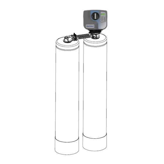
New Style Parallel Tank Connector
FOLLOWTHE INSTALLATION INSTRUCTIONS CAREFULLY. FAILURE TO
INSTALL THE UNIT PROPERLY VOIDS THE WARRANTY. BEFORE YOU
BEGIN INSTALLATION, READ THIS ENTIRE MANUAL. THEN, OBTAIN ALL
THE MATERIALS AND TOOLS
1. Avoid pinched o‐rings during installa on by applying (provided with install kit) NSF cer fied lubri‐
cant to all seals.
2. This system is not intended for trea ng water that is microbiologically unsafe or of unknown
quality without adequate disinfec on before or a er the system.
REVISION #
0
REVISION DATE May 4, 2015
54590-1
765 Valve
Filters
Advertisement
Table of Contents


Need help?
Do you have a question about the HT765TO-75 and is the answer not in the manual?
Questions and answers