Table of Contents
Advertisement
How To Install, Operate and
Maintain Your Reverse Osmosis
INSTALLERS: PLEASE READ ALL INSTRUCTIONS BEFORE IN-
STALLING AND USING THIS SYSTEM.
IT IS RECOMMENDED TO WAIT UNTIL THE ENTIRE SYSTEM IS
PRESSURIZED (INCLUDING STORAGE TANK & FAUCET) AND
RE-CHECK FOR ANY LEAKS BEFORE LEAVING INSTALLATION
SITE.
IT IS NORMAL FOR SOME BLACK CARBON FINES TO APPEAR
IN THE WATER WHEN EMPTYING THE FIRST 2 TANKS OF WA-
TER. THE FIRST 2 TANKS OF WATER PRODUCED SHOULD BE
EMPTIED AND NOT USED.
REVISION #
4
REVISION DATE NOVEMBER 7, 2012
Canature North America Inc.
System
Advertisement
Table of Contents

Related Manuals for Canature RO 75 GPD 4 STAGE


Summary of Contents for Canature RO 75 GPD 4 STAGE
- Page 1 Canature North America Inc. How To Install, Operate and Maintain Your Reverse Osmosis System INSTALLERS: PLEASE READ ALL INSTRUCTIONS BEFORE IN- STALLING AND USING THIS SYSTEM. IT IS RECOMMENDED TO WAIT UNTIL THE ENTIRE SYSTEM IS PRESSURIZED (INCLUDING STORAGE TANK & FAUCET) AND RE-CHECK FOR ANY LEAKS BEFORE LEAVING INSTALLATION SITE.
-
Page 2: Table Of Contents
Table of Contents PAGE How Your System Works Before You Start Tools Needed System Location Parts of the System Installing the Filters Installing the Membrane Installing the Tank Ball Valve Installing the Faucet Installing the Self-Piercing Inlet Saddle Valve Installing the Drain Saddle Installing the Unit Installing Tubing Into Fittings Sanitize the System... -
Page 3: Before You Start
Before You Start Your system contains filters which must be replaced periodically for proper operation. (Refer to Filter Change Schedule on page 9.) Read all steps and guides carefully before installing and using your RO system. Follow all steps exactly to correctly install. -
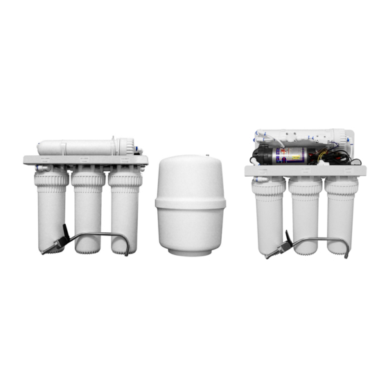
Page 4: Parts Of The System
Parts Of The System Reverse Osmosis Membrane Pre-Carbon Filter re- Pre-filter removes larger reduces dissolved minerals, met- moves chlorine in the feed particles such as sand, silt, als and salts. During the proc- water to protect the re- and rust. ess, harmful compounds are verse osmosis membrane. -
Page 5: Installing The Membrane
Installing the Membrane When handling membranes be sure hands are clean and sanitized or wear surgical gloves. Remove the blue quick connect clip and pull the inlet tubing to the membrane cap out. Loosen and remove RO membrane cap using wrench provided. Using scissors or a knife, cut the end of the plastic wrapper from the membrane. -
Page 6: Installing The Faucet
Installing the Faucet If the sink has a sprayer it may be disconnected for faucet installation. A pipe cap or plug will be necessary to seal the sprayer connection. The faucet should be positioned so it empties into the sink and the spout swivels freely for convenience. If sink has a hole that can accommodate the RO faucet, no drilling is required. -
Page 7: Installing The Self-Piercing Inlet Saddle Valve
Installing the Self-Piercing Inlet Saddle Valve The self-piercing saddle valve is designed for use with 3/8” to 1/2” OD soft copper supply tubing. 1. Turn off cold water valve from under sink or main water line valve for whole house. 2. -
Page 8: Installing Tubing Into Fittings
Installing Tubing Into Fittings Step 1 Cut the tube square and remove burrs and sharp edges. Ensure that the outside diameter is free from score marks. For soft or thin walled plastic tubing we recommend the use of a tube insert. Step 2 Push the tube into the fitting and up to the tube stop Pull on the tube to check that it is secure. -
Page 9: Flush System And Check Operation
Flush System and Check Operation Start-up 1. Check all connections to be sure they are secure. 2. Turn on feed water valve and check for leaks. 3. Open faucet and bleed any air out. When air is removed, close faucet, wait 5 minutes and check for leaks. Flush System and Check Operation 1. -
Page 10: Trouble Shooting
1. Tubing connections not installed properly. 1. Re-install tubing into fitting. 2. Defective tubing. 2. Cut damage section of tubing and re-install. Spare Parts List - RO 75 GPD 4 STAGE RO 75 GPD 4 STAGE No. PART No. Description... -
Page 11: Flow And Electrical Diagrams
Spare Parts List - RO 75 GPD 4 STAGE BP RO 75 GPD 4 STAGE BP No PART No Description Material Quantity 41320004 CARTRIDGE HOUSING-10 65010001 SEDIMENT FILTER CARTRIDGE 10'',5 μm PP 41804003 EPDM CARTRIDGE HOUSING ORING 70020002 TANK 3.0 GALLON... -
Page 12: Warranty
Canature North America Inc. will replace any part which fails two (2) years from date of manufacture as indicated by the serial number or date code, provided the failure is due to a defect in material or workmanship.
Need help?
Do you have a question about the RO 75 GPD 4 STAGE and is the answer not in the manual?
Questions and answers