Sign In
Upload
Manuals
Brands
Phoenix Contact Manuals
Microphone system
RAD-900-DAIO6
Phoenix Contact RAD-900-DAIO6 Manuals
Manuals and User Guides for Phoenix Contact RAD-900-DAIO6. We have
1
Phoenix Contact RAD-900-DAIO6 manual available for free PDF download: User Manual
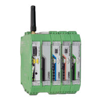
Phoenix Contact RAD-900-DAIO6 User Manual (140 pages)
900 MHz wireless transmission system for serial interfaces and I/O signals
Brand:
Phoenix Contact
| Category:
Microphone system
| Size: 8 MB
Table of Contents
Table of Contents
3
I/O Extension Modules
2
Table of Contents
3
1 For Your Safety
7
Labeling of Warning Notes
7
Qualification of Users
7
Safety Notes
8
Installation and Operation
8
Safety Regulations for Installation in Potentially Explosive Areas
9
Conformance
10
2 Short Description
11
RAD-900-IFS Wireless Module
11
RAD-900-IFS Structure
12
Structure
12
Rad-900-Daio6
13
RAD-900-IFS Circuit Diagram
13
RAD-900-DAIO6 Structure
14
Structure
14
DIP Switches of the RAD-DAIO6-IFS
15
3 Description of I/O Extension Modules
17
RAD-AI4-IFS - Analog Extension Module with Four Inputs
18
Structure
18
Basic Circuit Diagram
19
Basic Circuit Diagram for the RAD-AI4-IFS
19
DIP Switches of the RAD-AI4-IFS
19
Setting the DIP Switches
19
Diagnostic Leds
20
Diagnostic Leds of the RAD-AI4-IFS
20
Process Data in Plc/Modbus RTU Mode
21
Setting the I/O-MAP Address
21
Setting the I/O-MAP Address for the RAD-AI4-IFS
21
RAD-PT100-4-IFS - Extension Module with Four Temperature Inputs
22
2-Wire Connection Technology
22
Connecting Sensors
22
4-Wire Connection Technology
24
Measuring Errors Using 2-Wire Connection Technology
24
Systematic Temperature Measuring Error ΔT Depending on the Cable
24
Systematic Temperature Measuring Error ΔT Depending on the Cable Cross Section a
25
Temperature TA
25
Shielding of the Sensor Cables
26
Shielding with 3-Wire Connection Technology
26
3-Wire Connection Technology
27
Structure
27
Basic Circuit Diagram
28
Basic Circuit Diagram for the RAD-PT100-4-IFS
28
Diagnostic Leds
28
Diagnostic Leds of the RAD-PT100-4-IFS
28
Process Data in Plc/Modbus RTU Mode
29
Setting the I/O-MAP Address
29
Setting the I/O-MAP Address for the RAD-PT100-4-IFS
29
RAD-AO4-IFS - Analog Extension Module with Four Outputs
30
Structure
30
Basic Circuit Diagram
31
Basic Circuit Diagram for the RAD-AO4-IFS
31
DIP Switches of the RAD-AO4-IFS
31
Setting the DIP Switches
31
Diagnostic Leds
32
Diagnostic Leds of the RAD-AO4-IFS
32
Process Data in Plc/Modbus RTU Mode
33
Setting the I/O-MAP Address
33
Setting the I/O-MAP Address for the RAD-AO4-IFS
33
RAD-DI4-IFS - Digital Extension Module with Four Inputs
34
Structure
34
Basic Circuit Diagram
35
Basic Circuit Diagram for the RAD-DI4-IFS
35
Diagnostic Leds
35
Figure 3-23 Diagnostic Leds of the RAD-DI4-IFS
35
Process Data in Plc/Modbus RTU Mode
36
Setting the I/O-MAP Address
36
Setting the I/O-MAP Address for the RAD-DI4-IFS
36
RAD-DI8-IFS - Digital Extension Module with Eight Inputs
37
Figure 3-24 RAD-DI8-IFS Structure
37
Structure
37
Basic Circuit Diagram
38
Figure 3-25 Basic Circuit Diagram for the RAD-DI8-IFS
38
Setting the DIP Switches
38
DIP Switches of the RAD-DI8-IFS
39
Figure 3-26 DIP Switches of the RAD-DI8-IFS
39
Functions in Pulse Counter Mode
39
Diagnostic Leds
40
Figure 3-27: Diagnostic Leds of the RAD-DI8-IFS
40
Setting the I/O-MAP Address
41
Setting the I/O-MAP Address for the RAD-DI8-IFS
41
Process Data in Plc/Modbus RTU Mode
42
RAD-DOR4-IFS - Digital Extension Module with Four Outputs
43
Figure 3-28 RAD-DOR4-IFS Structure
43
Structure
43
Basic Circuit Diagram
44
Figure 3-29: Basic Circuit Diagram for the RAD-DOR4-IFS
44
Figure 3-30: DIP Switches of the RAD-DOR4-IFS
44
Setting the DIP Switches
44
Diagnostic Leds
45
DIP Switches of the RAD-DOR4-IFS
45
Figure 3-31 Diagnostic Leds of the RAD-DOR4-IFS
45
Setting the I/O-MAP Address
46
Setting the I/O-MAP Address for the RAD-DOR4-IFS
46
RAD-DO8-IFS - Digital Extension Module with Eight Outputs
47
Figure 3-32 RAD-DO8-IFS Structure
47
Structure
47
Basic Circuit Diagram
48
Figure 3-33 Basic Circuit Diagram for the RAD-DO8-IFS
48
Setting the DIP Switches
48
Diagnostic Leds
49
DIP Switches of the RAD-DO8-IFS
49
Figure 3-34 DIP Switches of the RAD-DO8-IFS
49
Figure 3-35 Diagnostic Leds of the RAD-DO8-IFS
49
Process Data in Plc/Modbus RTU Mode
51
Setting the I/O-MAP Address
51
Setting the I/O-MAP Address for the RAD-DO8-IFS
51
RAD-DAIO6-IFS - Analog/Digital Extension Module with Six Channels
52
Figure 3-36 RAD-DAIO6-IFS Structure
53
Structure
53
Basic Circuit Diagram
54
Figure 3-37 Basic Circuit Diagram for the RAD-DAIO6-IFS
54
Figure 3-38 DIP Switches of the RAD-DAIO6-IFS
54
Setting the DIP Switches
54
Diagnostic Leds
55
DIP Switches of the RAD-DAIO6-IFS
55
Figure 3-39 Diagnostic-Leds of the RAD-DAIO6-IFS
55
Setting the I/O-MAP Address
56
Setting the I/O-MAP Address for the RAD-DAIO6-IFS
56
Process Data in Plc/Modbus RTU Mode
57
RAD-RS485-IFS Modules
57
Figure 3-40: Typical RAD-RS485-IFS Installation
57
4 Installation
59
DIN Rail-Mounted Devices (RAD-900-IFS)
59
Figure 4-1 Radioline Connection Station with up to 32 I/O Extension Modules
59
Mounting/Removal
59
Figure 4-2 Mounting and Removal
60
Connecting the Power Supply
61
Connecting Wires
61
Figure 4-3 Connecting Wires
61
Figure 4-4 Connecting the Power Supply
62
Serial Interfaces
62
Figure 4-5: RS-485 Interface Pin Assignment
63
Figure 4-6: RS-232 Interface Pin Assignment (DTE - DCE)
63
Figure 4-7: RS-232 Interface Pin Assignment (DTE - DTE)
63
Connecting the Antenna
64
Figure 4-8 D-SUB 9 Straight-Through Cable Pinouts for 3-Wire (A) and 5-Wire (B)
64
Figure 4-9 D-SUB 9 Null Cable Pinouts for 3-Wire (A) and 5-Wire (B)
64
Wall-Mounted Devices (RAD-900-DAIO6)
65
Figure 4-10 Connecting the Antenna
65
Figure 4-11 Mounting Feet
65
Mounting
65
Connecting Wires
66
Figure 4-12 Mounting Dimensions
66
Wire Entry
66
Connecting Power
67
Figure 4-13 Zip Ties
67
Connecting the Antenna
68
5 Configuration and Startup
69
Default Settings of the Wireless Module
69
Resetting to the Default Settings
69
Firmware Update
70
Operating Mode of the Wireless Module
70
Configuration Via PSI-CONF Software
70
Setting the Address of the Wireless Module Via the Thumbwheel
73
Configuration Via CONFSTICK
73
Copying Device Settings Via Memory Stick
75
Saving Parameters from the Wireless Module to the Memory Stick
75
Reading the Memory Stick
76
Configuration Via PSI-CONF Software
76
Data Transmission Speed of the Wireless Interface
77
Extended Configuration, Individual Settings
77
Device Settings
79
Starting up I/O Extension Modules
81
Combinations of Extension Modules
81
Setting the Address of the Extension Modules Via the Thumbwheel
82
Wireless Module in Plc/Modbus RTU Dual Mode
83
Starting up the RAD-900-DAIO6
84
Setting the Address of the RAD-900-DAIO6 Via the Thumbwheel
84
RAD-900-DAIO6 in Plc/Modbus RTU Dual Mode
85
Startup Time of the Wireless Station
86
6 Serial Data Mode (RAD-900-IFS Only)
87
Frame-Based Data Transmission
89
7 Plc/Modbus RTU Mode
91
Configuration Via PSI-CONF Software
91
Configuration Via PSI-CONF Software
92
Addressing I/O Extension Modules
93
Watchdog
93
2/138 PHOENIX CONTACT 3827_En_B
94
8 Plc/Modbus RTU Dual Mode
95
Configuration Via PSI-CONF Software
96
Addressing I/O Extension Modules
97
Watchdog
97
9 Addressing I/O Extension Modules and RAD-900-DAIO6 with Modbus RTU
99
Modbus Function Codes
99
Modbus Protocol
99
Addressing Registers
100
Modbus Protocol: Structure of Telegrams (Frames)
100
Module Type and Error Code Register
101
Module Type Ids
101
Assigning I/O Extension Modules to the Register
102
Modbus Memory Map
102
RAD-AI4-IFS Process Data
103
RAD-PT100-4-IFS Process Data
104
RAD-AO4-IFS Process Data
105
RAD-DI4-IFS Process Data
106
RAD-DI8-IFS Process Data
106
RAD-DOR4-IFS Process Data
108
RAD-DO8-IFS Process Data
109
RAD-DAIO6-IFS and RAD-900-DAIO6 Process Data
110
Complete Overview of the Modbus Memory Map
111
Error Codes and Formats for Analog Input and Output Values
114
Representation of Analog RAD-AI4-IFS Values
114
Representation of Analog RAD-AO4-IFS Values
114
Representation of Analog RAD-DAIO6-IFS Values
114
RSSI Signal Register
115
Representation of the RAD-PT100-4-IFS Pt 100 Values
115
10 Detecting and Removing Errors
117
RSSI Voltage
117
Detecting and Removing Errors: Wireless Module
118
Detecting and Removing Errors: I/O Extension Module
122
Loopback Test During Serial Data Transmission
123
11 Diagnostics on the Wireless Module
125
Diagnostic Leds
125
LED Bar Graph
127
Diagnostics Via PSI-CONF Software
130
Recording Parameters
132
12 Appendixes
133
12 2 List of Tables Section 2
137
Advertisement
Advertisement
Related Products
Phoenix Contact RAD-2400-IFS
Phoenix Contact RAD-ISM-2400-SET-UD-ANT
Phoenix Contact RAD-900-IFS
Phoenix Contact RAD-868-IFS
Phoenix Contact RAD-UHF-FL-RS232-BD/63F01
Phoenix Contact RAD-UHF-FL-RS232-BD/51F01
Phoenix Contact RAD-SOL-SET-24-200
Phoenix Contact RAD-SOL-PAN-12-50
Phoenix Contact RAD IFS Series
Phoenix Contact RAD-AI4-IFS
Phoenix Contact Categories
Controller
Switch
Power Supply
Control Unit
Industrial Equipment
More Phoenix Contact Manuals
Login
Sign In
OR
Sign in with Facebook
Sign in with Google
Upload manual
Upload from disk
Upload from URL