Table of Contents
Advertisement
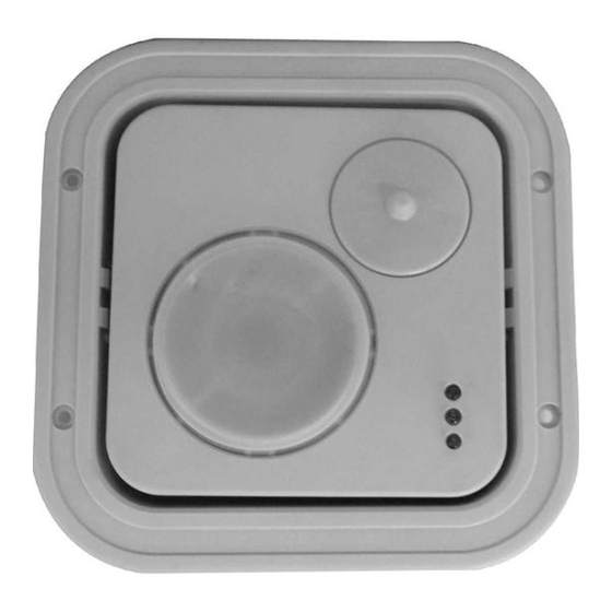
Model DT-6360STC
Ceiling Mount Motion Sensor
INSTALLATION INSTRUCTIONS
MOUNTING LOCATION
The DUAL TEC
6360STC motion sensor provides maximum
®
coverage when mounted on ceilings from 8' (2.4 m) to 16' (4.8 m)
high. Refer to the System Set-up section to determine which
passive infrared (PIR) mirror assembly to use at different ceiling
heights.
Choose a mounting location in the center of the protected area.
The protected area should be free of objects that might prevent
the PIR sensor from detecting an intruder: large pieces of
furniture, room dividers, etc.
Remember, infrared energy cannot penetrate solid objects. If the
PIR detector is blocked, the DT-6360STC will not trigger an alarm.
Note: If you plan to use the DT-6360STC's tamper switches,
read the Tamper Installation section on page 1.
MOUNTING PROCEDURE
To remove the front cover, orient the DT-6360STC so that one of
the sides with the small rectangular slot in the center is visible.
Using a small flathead screwdriver, gently push down on the slot
while separating the housing parts. Set the front cover aside.
Remove the printed circuit board (PCB) by depressing one of
the retaining brackets at its sides. Use the microwave antenna
to carefully pull the PCB out.
Surface Mounting
If mounting the DT-6360STC directly on a ceiling, use the back
cover as a template to mark holes for the mounting screws and
Wiring. Drill the holes. Then pull several inches of wiring from
the ceiling through the center hole in the back housing.
Attach the back housing to the ceiling with the mounting screws.
Recommended mounting screws: #6 (M3.5) pan head.
Note: If surface wiring, use the knockout hole on the side of the
housing.
IMPORTANT:
To ensure insects do not get inside the DT-
6360STC housing, make sure to seal all holes. (Recommended
sealant: silicone RTV.)
Flush Mounting
The DT-6360STC is shipped with a special kit for flush mount-
ing. The kit contains a recess "bucket" and retainer ring. The
retainer ring is only needed when flush mounting the unit in
ceiling tile. Removing the tile from the ceiling (if possible) will
make the installation process easier.
To flush mount the unit, cut a 5.5" x 5.5" (14 cm x 14 cm) hole in
the ceiling. Insert the recess bucket into the hole, using it as a
template to mark drill holes for the four mounting screws.
Remove the bucket and drill the screw holes.
If using the retainer ring, place it through, then directly over, the
hole in the ceiling tile. Make sure to orient the retainer ring
and recess bucket as shown in Figure 1.
Next, attach the back housing of the DT-6360STC to the inside
of the recess bucket, using the same screw holes and screws
used for surface mounting [#6 (M3.5) pan head]. Pull several
inches of wiring from the ceiling through the center hole in the
recess bucket and DT-6360STC back housing.
Insert the recess bucket into the hole in the ceiling, securing it to
the ceiling (and retainer bracket) with four mounting screws.
RETAINER
RING
CEILING
Figure 1
DT-6360STC
Flush Mounting Kit
Tamper Installation
The DT-6360STC is equipped with two tamper switches: a cover
tamper and ceiling tamper. When the tamper switches are used,
removing the cover from the sensor will activate the cover tamper;
removing the sensor from the ceiling will activate the ceiling
tamper. Both tamper switches are normally closed (NC) and
internally wired in series.
The cover tamper switch can be used without the ceiling tamper
and requires no modifications to the DT-6360STC housing.
To use the ceiling tamper, remove the square knockout in the rear
housing (directly behind the ceiling tamper switch), then install a
screw* in the ceiling. Leave enough of the screw protruding to
depress the tamper switch. Refer to Figure 2.
If the installation is recessed, remove the knockout from the rear
housing, drill a screw hole (behind the knockout) in the recess
bucket, then install the screw* in the recess bucket. Leave
enough of the screw protruding to depress the tamper switch.
Refer to Figure 2.
*Note: #6 (M3.5)
pan head is
recommended.
KNOCKOUT
LATCH
SURFACE MOUNT
Screw
to depress
DT-6360STC
tamper
- 1 -
Figure 2
Cover and Ceiling
REAR HOUSING
Tamper Switches
KEYHOLE
PIN FOR PCB
FLUSH MOUNT
CEILING
CEILING
Screw
to depress
DT-6360STC inside
tamper
recess bucket
RECESS
BUCKET
DT-6360STC
Advertisement
Table of Contents

Related Manuals for Honeywell DT-6360STC


Summary of Contents for Honeywell DT-6360STC
- Page 1 MOUNTING PROCEDURE and requires no modifications to the DT-6360STC housing. To remove the front cover, orient the DT-6360STC so that one of To use the ceiling tamper, remove the square knockout in the rear the sides with the small rectangular slot in the center is visible.
- Page 2 Removing Front Cover After Installation (flush mount) SYSTEM TESTING After installing and walk-testing the DT-6360STC flush mount, you DT-6360STC sensors are equipped with two diagnostic LEDs: may need to make adjustments. Use a screwdriver to reopen the green for PIR and yellow for microwave. The red LED is used to front cover.
- Page 3 W3, the LEDs will display an INFORMER trouble code, but there will be no trouble output. See Figure 5.) DT-6360STC sensors use the event sequence in Figure 6 The DT-6360STC immediately performs a self-test to determine (below) to determine an alarm: if the problem is internal.
- Page 4 Troubleshooting Matrix TROUBLE MEMORY Connect the pins with the screwdriver again to clear the LED When the DT-6360STC signals a trouble output, the LEDs display pattern. a failure pattern — all three LEDs flash at the same rate. Notes: The Trouble Memory only stores a single event (the last You can recover the individual pattern to determine what trouble event to occur) in memory.
-
Page 5: Product Specifications
1 look-down Important Notices *The ULC label or listed marking on a product is the only evidence The DT-6360STC should be tested at least once each year to provided by Underwriters Laboratories of Canada to identify products ensure proper operation. - Page 6 (2) this device must accept any interference, including is cautioned that changes or modifications not expressly approved by Honeywell could void the user's authority to operate this equipment. interference that may cause undesired operation of the device. This Class B digital apparatus meets all requirements of the Canadian This equipment has been tested and found to comply with the limits for a Interference-Causing Equipment Regulations.
Need help?
Do you have a question about the DT-6360STC and is the answer not in the manual?
Questions and answers