Table of Contents
Advertisement
Quick Links
MPORTA
Retain
product
285 2.1‐110 0 316
Pow
wer C
Cage A
TANT: Rea
d all inst
tructions c
this owner
r's manual
l for future
t may vary
y from this p
Attac
chmen
carefully b
before us
e reference
e. The spe
photo and
d, subject to
o change w
nt
sing this p
product.
ecifications
s of this
without no
tice.
Advertisement
Table of Contents

Related Manuals for Fitness Reality XCLASS Series


Summary of Contents for Fitness Reality XCLASS Series
- Page 1 wer C Cage A Attac chmen MPORTA TANT: Rea d all inst tructions c carefully b before us sing this p product. Retain this owner r’s manual l for future e reference e. The spe ecifications s of this product t may vary y from this p...
- Page 2 STOP ARRÊT ALTO PLEASE DO NOT RETURN THIS PRODUCT TO THE STORE. If you need help with product information, assembly, or replacement parts. Please contact customer service. Email us at: Service@paradigmhw.com Or call us at: 1-844-641-7920 Hours: 8:00 am to 5:00 pm (PST) Daily ...
-
Page 3: Table Of Contents
TABLE OF CONTENTS SERVICE-------------------------------------------------------------------- LABEL PLACEMENT----------------------------------------------------- PRODUCT SAFETY------------------------------------------------------ ASSEMBLY PREPARATION-------------------------------------------- PRODUCT DRAWING--------------------------------------------------- OVERVIEW------------------------------------------------------------------ 7 HARDWARE PACK-------------------------------------------------------- 8 PART LIST------------------------------------------------------------------- STEP 1----------------------------------------------------------------------- STEP 2----------------------------------------------------------------------- STEP 3----------------------------------------------------------------------- STEP 4----------------------------------------------------------------------- STEP 5----------------------------------------------------------------------- STEP 6----------------------------------------------------------------------- STEP 7----------------------------------------------------------------------- OPTIONAL------------------------------------------------------------------- 24 LUBRICATION------------------------------------------------------------- WARRANTY----------------------------------------------------------------- PARTS REQUEST FORM-----------------------------------------------... -
Page 4: Service
SERVICE IMPORTANT: FOR NORTH AMERICA ONLY For damage or defective product, questions, replacement parts or any other service support, please contact our customer service department (8:00 AM - 5:00 PM Pacific Standard Time, Open Daily) by below methods: For Best Service Email: Service@paradigmhw.com Website: www.paradigmhw.com... -
Page 5: Label Placement
LABEL PLACEMENT ... -
Page 6: Product Safety
PRODUCT SAFETY WARNING: Before using this equipment you should consult with your personal physician to see if the equipment is appropriate for you. Do not use this equipment without your physician’s approval. Do not use this equipment if you have any of the following conditions or ailments: ... -
Page 7: Assembly Preparation
ASSEMBLY PREPARATION Warning: It is highly recommend that you have assistance during the assembly of the strength equipment. 1. Tools for assembly: General tools you may needed for the assembly of the strength equipment. Metric Allen Key Set Metric Wrench Set and Adjustable Wrench ... -
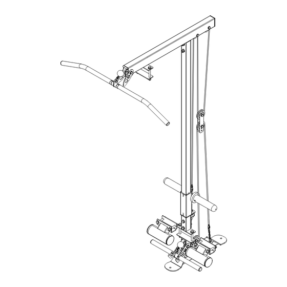
Page 8: Product Drawing
PRODUCT DRAWING ... -
Page 9: Overview
OVERVIEW DRAWING ... -
Page 10: Hardware Pack
HARDWARE PACK ... -
Page 11: Part List
PART LIST Part# Description Q’ty. Part# Description Q’ty. BUTTON ALLEN BOLT BASE ASSEMBLY M10x1.5x15L SLIDER BAR MOUNT WASHER D11xD20x2.0 UPPER PIPE ASSEMBLY WASHER D13xD24x2.5 SLIDER BAR NYLON NUT M10 SLIDER NYLON NUT M12 RECTANGLE END CAP FOOT REST 75x50x2 FOOTPLATE PADS PULLEY PLATE 100x80x5.0 OLYMPIC PLATE STOPPER... - Page 12 STEP 1 1A. Slide the Base Assembly (A) underneath the Stability Beam (K-6877) and align it with the bolt holes on the bottom side of the Stability Beam (K-6877). 1B. Place and align the Slide Bar Mount (B) with the bolt holes on the top side of the Stability Beam (K-6877) 1C.
- Page 13 STEP 1 Wrench 2PCS K-6877 NO.52 Washer NO.16 Hex Bolt NO.76 Nylon Nut D13xD24x2.5 M12x1.75x105L M12 2PCS 4PCS 2PCS...
- Page 14 STEP 2 2A. Attach the two Foot Rests (F) and two Connecting Plates (K) to the Stability Beam (K-6877) by using: 4 - (7) Hex Bolt M12x1.75x80L 8 - (52) Washer D13xD24x2.5 4 - (76) Nylon Lock Nut M12 Thoroughly tighten the hardware once complete.
- Page 15 STEP 2 Wrench 2PCS NO.7 Hex Bolt NO.52 Washer NO.76 Nylon Nut M12x1.75x80L D13xD24x2.5 M12 4PCS 4PCS 8PCS...
- Page 16 STEP 3 3A. Insert the Slider Bar (D) into the Slider Bar Mount (B) and hold the Slider Bar (D) in place. 3B. Align the bolt holes of the Stopper Plate (H) with the bolt holes at the rear of the Slider Bar Mount (B) and fasten the Stopper Plate (H), Slider Bar (D), and Slider Bar Mount (B) together by using : 2 - (22) Hex Bolt M12x1.75x75L 4 - (52) Washer D13xD24x2.5...
- Page 17 STEP 3 Wrench 2PCS NO.22 Hex Bolt NO.52 Washer NO.76 Nylon Nut M12x1.75x75L D13xD24x2.5 M12 2PCS 2PCS 4PCS...
- Page 18 STEP 4 4A. Insert the Upper Pipe Assembly (C) into the Slider Bar (D) and secure it by using: 2 - (26) Hex Bolt M12x1.75x70L 4 - (52) Washer D13xD24x2.5 2 - (76) Nylon Lock Nut M12 4B. Attach the Upper Pipe Assembly (C) and one Connecting Plate (K) to the Rear Crossbeam (G-6877) by using: 2 - (16) Hex Bolt M12x1.75x105L 4 - (52) Washer D13xD24x2.5...
- Page 19 STEP 4 Wrench 2PCS NO.16 Hex Bolt NO.76 Nylon Nut NO.52 Washer NO.26 HEX BOLT M12x1.75x105L M12 4PCS D13xD24x2.5 M12x1.75x70L 2PCS 2PCS 8PCS...
- Page 20 STEP 5 5A. In preparation for the installation of the pulleys in step 6 take the Upper Cable (291) and feed the smaller end into Upper Pipe Assembly (C) until it can be pulled out from the furthest hole at the opposite end of Upper Pipe Assembly (C).
-
Page 21: Step
STEP 5... -
Page 22: Step 6
STEP 6 6A. Install the two Wide Groove Pulleys (L) at the locations shown in the diagram AA-1 by using: 2 - (25) Hex Bolt M10x1.5x65L 4 - (51) Washer D11xD20x2.0 2 - (75) Nylon Lock Nut M10 6B. Install the five Pulleys (228) at the locations shown in the diagrams by using: 3 - (24) Hex Bolt M10x1.5x50L 2 - (25) Hex Bolt M10x1.5x65L... -
Page 23: Step 6
STEP 6 Wrench 2PCS AA-1 AA-2 NO.25 HEX BOLT NO.24 HEX BOLT NO.75 NYLON NUT NO.51 WASHER M10x1.5x65L M10x1.5x50L M10 7PCS D11xD20x2.0 4PCS 3PCS 10PCS... -
Page 24: Step 7
STEP 7 7A. To adjust the Length of the Lower Cable (292) use the Chain (294) and an additional Hook (293) to give a comfortable length to workout with. 7B. To adjust the Length of the Upper Cable (291), change the location at which the Pulleys (228) are mounted to the Pulley Plates (G). -
Page 25: Step 7
STEP 7 Hole options of the Pulley Plate (G) parts are for adjusting the slack of the cables as the cable ages. Use the Hook (293) and the loops of the Chain (294) to adjust the slack of the cable. -
Page 26: Optional
Optional 4mm Allen Wrench 1PC If you would like to use the available Olympic Plate Adaptors for Olympic sized plates, please follow the steps below: A. Use a 4 mm Allen key to loosen the Allen screws of the Olympic Plate Adaptors (226). - Page 27 Optional When using standard size 1” inch plates, use the available Standard Clips. To install the Standard Clips, please follow the steps below: A. Pinch the rubber grips of Standard Clip (294). B. Slide a Standard Clip (294) on to each post of the Slider (E).
-
Page 28: Lubrication
LUBRICATION Lubrication The machine must be lubricated periodically. ONLY USE SILICONE OIL when lubricating the Slider Bar (D). A. Wipe the Slider Bar (D) clean using a dry cloth. Be sure to clean off any dried oil. Remove the Silicone Oil from the Manual pack and cut the lid off using a pair of scissors. -
Page 29: Warranty
WARRANTY MANUFACTURER’S LIMITED WARRANTY Paradigm Health & Wellness guarantees to the original purchaser that this product is free from defects in material and workmanship when used for the purpose intended, under the conditions that it has been installed and operated in accordance with Paradigm’s Owner’s Manual. -
Page 30: Parts Request Form
PARTS REQUEST FORM Paradigm Health & Wellness, Inc. EMAIL THIS FORM WITH YOUR RECIEPT OF PURCHASE TO Service@paradigmhw.com * NAME: _______________________________________________________ ADDRESS: ____________________________________________________ CITY ______________ STATE ______________ ZIP ___________________ TELEPHONE: (Day) ____________________________________________ (Night) ____________________________________________ SERIAL#: _____________________________________________________ MODEL#: _____________________________________________________ PURCHASE DATE: _____________________________________________ PLACE OF PURCHASE: _________________________________________ PART # DESCRIPTION “YOUR ORDER WILL BE PROCESSED WITHIN 3 BUSINESS DAYS”...
Need help?
Do you have a question about the XCLASS Series and is the answer not in the manual?
Questions and answers