Table of Contents
Advertisement
Advertisement
Table of Contents

Related Manuals for Ivoclar Vivadent IvoBase Series


Summary of Contents for Ivoclar Vivadent IvoBase Series
- Page 1 IvoBase Injector ® Operating Instructions...
-
Page 2: Table Of Contents
Table of Contents List of parts Introduction / Signs and Symbols 1.1 Preface 1.2 Introduction 1.3 Notes regarding the Operating Instructions 1.4 Note on the different voltage versions Safety First 2.1 Indications 2.2 Health and safety instructions Product Description 3.1 Components 3.2 Hazardous areas and safety equipment 3.3 Functional description Installation and Initial Start-Up... -
Page 3: List Of Parts
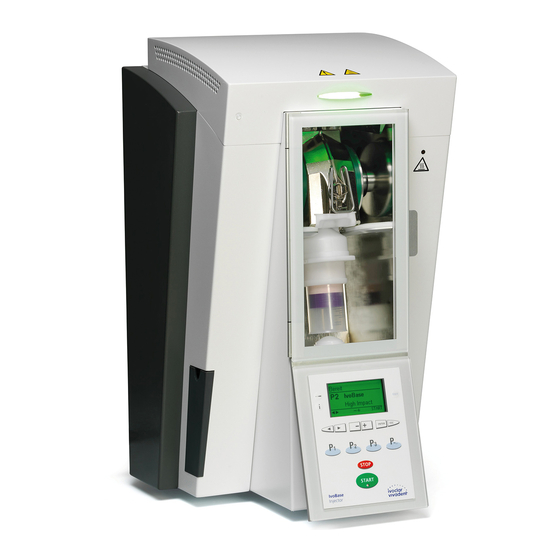
List of Parts Injector: Temperature sensor Heater Warnings Operating Status Display (OSD) Warning light Clasps Door handle Polymerization chamber Injection head 10 Operating panel Rubber feet Waste water container Power cord Housing Capsule Safety door Flask 18 Knurled screw for hood Air vents 20 On/Off switch Power socket... - Page 4 Flask: 40 Isolating shoulder 45 Locking clasp 46 Recess for the aeration filter Centering peg 42 Flask lid 47 Screws 43 Flask housing 48 Heating surface 49 Sensor surface 44 Locking clasp attachment 61 Access former half 62 Access former full 63 Centring insert Deflasking aid...
- Page 5 Operating panel 71 Settings key 72 Information key 73 Right cursor key Left cursor key 75 Program 2 key 76 Program 1 key 77 RMR key 78 – key 79 + key 80 ESC key 81 ENTER key 82 Next Program Number key 83 Program 3 key 84 STOP key 85 START key...
-
Page 6: Introduction / Signs And Symbols
IvoBase Injector. Should you lose the Operating Enjoy working with the IvoBase Injector. Instructions, extra copies can be ordered at a nominal fee from your local Ivoclar Vivadent Service Centre or downloaded in the Down- load Center at www.ivoclarvivadent.com/downloadcenter. 1.2 Introduction 1.4 Note on the different voltage versions... -
Page 7: Safety First
2. Safety First This chapter is especially important for individuals who 2.1.1 work with the IvoBase Injector or who have to carry out maintenance or repair work. This chapter must be read Risks and dangers and the corresponding instructions followed! Make sure that no liquids or other 2.1 Indications foreign substances enter the... - Page 8 2.1.5 2.1.9 Contraindication Contraindication The hood may only be removed Foreign objects must not enter while the injector is switched off the air vents. and the power plug disconnect- 2.1.6 2.1.10 Contraindication Contraindication The locking clasp may only be removed from the flask by rotat- The injector must not be operated ing, rather than pushing it.
-
Page 9: Health And Safety Instructions
Information regarding disposal can be found on the respective national Ivoclar Vivadent website. – Always keep the air vents unobstructed. – Do not touch any parts that become hot during operation of the injector. -
Page 10: Product Description
3. Product Description 3.1 Components Functional description The IvoBase Injector comprises the following components: The IvoBase Injector has been developed for the IvoBase System and – Basic injector with polymerization chamber and operating panel allows an automated and controlled injection process. The injector –... -
Page 11: Installation And Initial Start-Up
Check the delivery for completeness (see delivery form in Chapter 9) and transportation damage. If parts are damaged or missing, con- tact your local Ivoclar Vivadent Service Centre. Packing and shipping The packaging may be discarded with the regular house- hold refuse. -
Page 12: Establishing The Connections
4.4 Establishing the connections Power connection Please make sure that the voltage indicated on the rating plate complies with the local power supply. Subsequently, connect the power cord (13) with the power socket of the injector (21). Connect the USB download cable. If required, e.g. -
Page 13: Initial Start-Up
4.5 Initial start-up 1. Connect the power cord (13) with the wall socket. 2. Put the On/Off switch (20) on position "I". Immediately after switching on, the display shows the start screen for a few seconds. The injector now conducts an automatic self-test. During the test, the performance of all injector components is automatically checked. -
Page 14: Operation And Configuration
5. Operation and Configuration 5.1 Introduction to the operation Function The IvoBase Injector is equipped with a graphic display with back- Information lighting. The injector can be operated by means of the membrane- Serial number, software versions, etc. sealed keypad. The input and command keys can be used to program and control the injector. -
Page 15: Settings And Information
5.4 Settings and information Indication on Settings Short description display By pressing the "Settings" key (71) you can access the General write Permits activation or settings screen (the latest selected settings will be indicated). protection deactivation of the general write protec- tion (using –... -
Page 16: Explanation Of The Symbols On The Display
5.6 Description of the beeper sounds Indication on Settings Short description display Basically, the beeper tune and volume set by the user are used for all acoustic signals. The acoustic signal can be stopped by pressing STOP. Date of the latest calibration 1. -
Page 17: Practical Use
6. Practical Use 6.1 Switching on the injector Please read the following processing notes carefully. Put the On/Off switch (20) on position "I". The injector now con- ducts an automatic self-test. Make sure that the injector is not manipulated during that time. –... - Page 18 If the safety door is opened while an injection pro- gram is running, the program is stopped for safety reasons. While the program is interrupted, the green LED in the START key flashes. The process is automatically resumed once the door has been closed.
-
Page 19: Maintenance, Cleaning And Diagnosis
All other tasks must be per- the injector, which is discharged via a drain outlet. Check the water formed by qualified service personnel at a certified Ivoclar Vivadent level at regular intervals and empty the waste water container, if Service Centre. -
Page 20: Replacing The Temperature Sensor
7.4 Replacing the temperature sensor Step 2: Unplug the cable for the OSD. Before replacing the temperature sensor, disconnect the injector from the power supply. The temperature sensor of the IvoBase Injector has been developed in such a way that users may replace it by themselves, if required (cleaning, defect). -
Page 21: Cleaning
Step 2: Step 5: Clean the IvoBase polymerization chamber, heater and temperature Remove the sensor. Dismounted sensor: sensor while they are cold. Please make sure that the contact sur- faces of the heater and the temperature sensor are clean. Step 3: Close the flask with the locking clamps and attach a measuring point to the spot on the left flask... -
Page 22: Service Hint
When the Service Hint is displayed for the first time (Hint 1700), 3 years have passed or 10,000 cycles have been carried out. There- fore, Ivoclar Vivadent recommends having a maintenance procedure performed on the injector. The interval until the next appearance of the Service Hint can be changed in the Settings (see Section 5.4.1). -
Page 23: What If
A program in progress is aborted. *** Error cannot be acknowledged; programs cannot be started. If one of the following error codes is displayed, please contact the Ivoclar Vivadent After Sales Service directly. 25, 29, 54, 56,... -
Page 24: Resin Leaks From The Flask
8.2 Resin leaks from the flask 8.3 Resin leaks from the injection head Under certain circumstances – e.g. if the filter component was for- In case of a malfunction, resin may gotten to be placed in the flask (see Instructions for Use of the leak from the material capsule corresponding materials) –... -
Page 25: Technical Malfunctions
These malfunctions may occur without an error message being displayed: Error Double-check Measure Display incomplete Contact Ivoclar Vivadent After Sales Service. Text on the display is difficult to read. Is the contrast set correctly? Adjust the contrast. Display is not illuminated. -
Page 26: Product Specifications
9. Product Specifications 9.1 Delivery form 9.3 Acceptable operating conditions – IvoBase Injector Acceptable ambient temperature: – Power cord +5 °C to +40 °C / +41°F to +104 °F – USB download cable Acceptable humidity range: – 2 Sets of flasks Relative humidity 80% for temperatures up to 31 °C / 87.8 °F –... -
Page 27: Appendix
Program for the polymerization of the SR Ivocap Clear material with additional 65 min RMR, residual monomer <= 1.0% SR Ivocap Elastomer Program for the polymerization of the SR Ivocap Elastomer material 65 min 6–20 Ivoclar Vivadent – Spare Space for future Ivoclar Vivadent injection programs. - Page 28 Ivoclar Vivadent Ltda. Ivoclar Vivadent Marketing (India) Ivoclar Vivadent Liaison Office Alameda Caiapós, 723 Pvt. Ltd. Ivoclar Vivadent Polska Sp. z o.o. : Tesvikiye Mahallesi Centro Empresarial Tamboré 503/504 Raheja Plaza Al. Jana Pawla II 78 Sakayik Sokak CEP 06460-110 Barueri – SP...
Need help?
Do you have a question about the IvoBase Series and is the answer not in the manual?
Questions and answers
ivobase machine is frozen. will not release the flask. turning on and off doesnt make a difference
The provided context does not contain specific instructions for fixing a frozen Ivoclar Vivadent IvoBase Series machine that won't release the flask. However, you can try the following general troubleshooting steps:
1. Turn Off and Restart – Switch off the device and turn it back on to reset any errors.
2. Check for Errors – If an error code is displayed, check if it requires contacting Ivoclar Vivadent After Sales Service.
3. Inspect Connections – Ensure all plug-in connections are secure.
4. Check for Resin Leaks – If resin has leaked, clean the polymerization chamber and heater.
5. Manual Release – If safe, carefully attempt to release the flask manually following the correct procedure.
If the issue persists, contact Ivoclar Vivadent After Sales Service for assistance.
This answer is automatically generated