Table of Contents
Advertisement
Advertisement
Table of Contents

Related Manuals for Ivoclar Vivadent Programat EP 5000 G2


Summary of Contents for Ivoclar Vivadent Programat EP 5000 G2
- Page 1 Programat ® EP 5000 Operating Instructions...
-
Page 3: Table Of Contents
Table of Contents Views of the Furnace, List of Parts Introduction / Signs and Symbols 1.1 Preface 1.2 Introduction 1.3 Notes regarding the Operating Instructions 1.4 Notes on the different voltage versions Safety First 2.1 Indications 2.2 Health and safety instructions Product Description 3.1 Components 3.2 Hazardous areas and safety equipment 3.3 Functional description 3.4 Accessories Installation and Initial Start-Up 4.1 Unpacking and checking the contents 4.2 Selecting the location 4.3 Assembly... -
Page 4: Views Of The Furnace, List Of Parts
List of parts Sealing surface 35 Screw for cooling tray Furnace head sealing ring 36 Hood 3 Insulation 37 Knurled screw for hood 4 Thermocouple 38 Air vents furnace head Firing plate 2 39 Air vents rear panel Touch screen 40 Warnings Frame plate 41 Furnace head mounting mark QTK heating muffle 42 Furnace base mounting mark Housing base 43 Furnace head mounting 10 Keypad 44 Quartz-glass tube 11 On/Off switch 46 Vacuum hose 12 Heating element fuse 47 Silicone washer 13 Vacuum pump fuse... - Page 6 12 13 49 66 26 30 60 67 29...
- Page 7 Control unit: 70 Program key 71 ESC key 72 ENTER key 73 START key 74 Start LED 75 STOP key 76 + key 77 - key 78 Settings / information 79 Cursor key up 80 Cursor key down 90 Open furnace head 91 Close furnace head 92 Numeric keys 93 Firing / Pressing 94 Home key 95 Help key 96 Power Saving Key 100 Programat firing tray 101 Metal pin A 102 Metal pin B 103 Metal pin C...
-
Page 8: Introduction / Signs And Symbols
1. Introduction / Signs and Symbols 1.3 Notes regarding the 1.1 Preface 1.2 Introduction Operating Instructions Dear Customer The signs and symbols in these Operating Instructions facilitate Thank you for having purchased the finding of important points the Programat EP 5000/G2. It is and have the following Furnace concerned: a state-of-the-art furnace for meanings: Programat EP 5000/G2 dental applications. Target group: Risks and dangers Dental technologists The furnace has been designed according to the latest industry These Operating Instructions standards. Inappropriate use facilitate the correct, safe, and may damage the equipment and economic use of the Programat Important be harmful to personnel. Please EP 5000/G2 furnace. -
Page 9: Safety First
2. Safety First This chapter is especially important for personnel who work with the 2.1.1 Programat EP 5000/G2 or who have to carry out maintenance or Risks and dangers repair work. This chapter must be read and the corresponding instructions followed. The furnace head should not be removed from the furnace base as long as the furnace head is con- 2.1 Indications nected by means of the The Programat EP 5000/G2 must only be used to fire and/or press heater cable. dental ceramic materials and it should be used for this purpose only. Other uses than the ones stipulated, e.g. cooking of food, firing of other m aterials, etc. are contraindicated. The manufacturer does not assume any liability for damage resulting from misuse. The user is solely responsible for any risk resulting from failure 2.1.2 to observe these Instructions. Risks and dangers Further instructions to assure proper use of the furnace: Make sure that no liquids or other – The instructions, regulations, and notes in these Operating foreign objects enter the furnace. I nstructions must be observed. – The instructions, regulations, and notes in the material’s I nstructions for Use must be observed. - Page 10 2.1.6 2.1.11 Risks and dangers Risk of crushing and burn hazard Do not carry the furnace by the Never reach under the furnace cooling tray. head with the hand or other parts of the body during operation, since there is a risk of crushing and a burn hazard. 2.1.7 2.1.12 Risks and dangers Contraindication Do not carry the furnace head by Do not insert any foreign objects the cables, since the cables and into the air vents. There is a risk of connections may be damaged. electrical shock. 2.1.8 2.1.13 Risks and dangers Contraindication The furnace has an electric drive This product contains ceramic and must be operated by means fibres and may release fibre dust. of the electronic controls. Never Do not use compressed air, or open the furnace head by hand,...
-
Page 11: Health And Safety Instructions
2.2 Health and Safety Instructions – There is a burn hazard at the cooling tray if the furnace is continuously operated in the press mode (Stand-by = 700 °C). This furnace has been designed according to EN 61010-1 and has been shipped from the manufacturer in excellent condition as far as Any disruption of the protective conductor either inside safety regulations are concerned. To maintain this condition and to or outside the furnace or any loosening of the protective assure risk-free operation, the user must observe the notes and conductor connection may lead to danger for the user in warnings contained in these Operating Instructions. case of malfunction. Deliberate interruptions are not – Place furnace on a fire-proof table (observe local regulations, e.g. tolerated. Materials developing harmful gases must not distance to combustible substances or objects, etc.) be fired. – Always keep the air vents at the rear of the furnace free from Warnings regarding the removal of the heating muffle obstruction. T his product contains ceramic fibres and may release fibre – Do not touch any parts that become hot during the operation of dust. Fibre dust has proved to be carcinogenic in animal the furnace. There is a burn hazard! experiments. – Clean furnace only with a dry or slightly moist cloth. Do not use The heating muffle must only be disassembled by a certified After any solvents! Disconnect power before cleaning. -
Page 12: Product Description
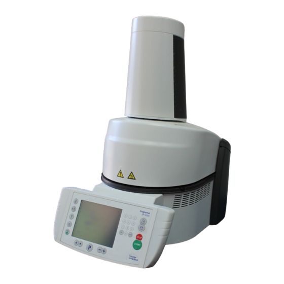
3. Product Description 3.1 Components 3.2 Hazardous areas and safety equipment The Programat EP 5000/G2 Description of the risk areas of the furnace: comprises the following Hazardous area Type of risk components: – Furnace base with electronic Firing chamber Risk of burning controls Opening/closing mechanism Risk of crushing – Furnace head with firing chamber and press drive Electrical components Risk of electrical shock – Firing plate – Cooling tray – Power cord and hose for v acuum pump Description of the safety equipment of the furnace: – Vacuum pump (accessory) Safety equipment Protective effect Protective conductor... -
Page 13: Installation And Initial Start-Up
4. Installation and Initial Start-Up 4.2 Selecting the location 4.1 Unpacking and checking the contents Place the furnace on a flat table using the rubber feet. Make sure The packaging provides the following advantages: – Reusable packaging that the furnace is not placed in the immediate vicinity of heaters or other sources of heat. Make sure that air may properly circulate – Closing mechanism with integrated transportation grips between the wall and the furnace. – Ideal protection by Styrofoam inserts – Easy handling / optimum unpacking Also ensure that there is enough space between the furnace and the – The packaging may be used in several ways (modules) user, as the furnace releases heat during the opening of the furnace head. Remove the furnace components from their packaging and place it on a suitable table. Please observe the instructions on the outer The furnace should neither be placed nor operated in areas packaging. - Page 14 Place the cooling tray (34) on the frame plate (7). Make sure that the cooling tray (34) is correctly positioned on the frame plate (7). Secure the cooling tray (34) with the two screws (35) including the silicone washer (47). Step 2: Mounting the furnace head The complete furnace head (58) is best mounted with the rear panel of the furnace pointing towards the user. Lift the furnace head with both hands (see picture) and carefully position it on the furnace head mounting (43).
- Page 15 Ensure that the furnace head mounting mark (41) is aligned with the furnace base mounting mark (42). M ake sure that the firing plate holder (48) is not damaged by mounting the furnace head. Step 3: Placing the firing plate for the investment ring (5) The firing plate for the investment ring (5) can now be placed on the firing plate holder (48). Step 4: Connections Connect the cables of the furnace head with the furnace base. Proceed as follows: – Insert the thermocouple plug (26) (make sure that the polarity of the plug is correct) – Insert the heater plug (28) – Insert the press drive plug (60)
- Page 16 Secure the heater plug (28) with the plug fuse (27) by turning it until the heater plug (28) has been secured. Step 5: Mounting the hood (36) Once all cables are properly connected to the furnace base, the hood (36) can be mounted. Subsequently, secure the hood with the knurled screw (37). The furnace may only be operated with the hood mounted. Step 6: Establishing additional connections Power connection Please make sure that the voltage indicated on the rating plate complies with the local power supply. Connect the power cord with the power socket (17) of the furnace. Vacuum pump connection Connect the vacuum pump plug with the vacuum pump socket (18). We recommend using only the VP4 vacuum pump from Ivoclar Vivadent, since this pump is especially coordinated with the Programat EP 5000/G2. If other pumps are used, please observe and do not exceed the maximum power consumption.
-
Page 17: Removing The Furnace Head
4.4 Removing the furnace head Before the hood (36) is removed, the furnace has to be switched off and the power cord disconnected from the power socket (17). 1. Loosen and remove the knurled screw (37) of the hood (36) 2. Remove the hood (36) 3. Disconnect the thermocouple plug (26) 4. Disconnect the heater plug (28) 5. Press the leaf spring (32) with a finger, lift off the furnace head at the same time and remove it Make sure the furnace head has completely cooled down before it is removed (fire hazard). -
Page 18: Initial Start-Up
4.5 Initial start-up 4.5.4 Setting the date Enter the date (day/month/year). 1. Connect the power cord with the wall socket. 2. Put the On/Off switch (11) at the rear of the furnace on position “I” and connect the vacuum pump. 4.5.1 Start screen Immediately after switching on, the display briefly shows the start screen. 4.5.5 Setting the time Enter the time (hours/minutes/ seconds). The furnace will now automatically conduct a self-test. The performance of all furnace components is automatically checked. The display shows the following indications during the self-test: 4.5.6 Selecting a reminder for the calibration interval In this screen, you may define at what interval the furnace should remind you to conduct the next temperature calibration procedure. Additional modifications can be carried out according to the point „Extended settings“. -
Page 19: Operation And Configuration
5. Operation and Configuration 5.1 Introduction to the operation START (Start LED) The Programat EP 5000/G2 is equipped with a colour graphical Starts the selected program. The fact that a display with backlighting. The furnace can be operated by means of program is running is indicated by the green LED. the keypad or touch screen. If the program is interrupted (1 x STOP), the Start The numeric and command keys can be used to program and LED flashes until renewed pressing of START control the furnace. results in the program being resumed. Ends an entry without accepting the value. Return from the current to the previous menu. Confirmation of error messages. Enter Confirmation of entered value. Numeric keypad, 1–9 and 0 Used to enter numeric values. Touch Screen 5.2 Explanation of the key functions The display is touch-sensitive. Slightly tapping it with the fingertip will result in the desired button being marked with a thick, black frame. After... -
Page 20: Program Structure
5.3.1 Firing programs Symbol Parameter Value range Value range All the firing programs are equivalent and, therefore, full-fledged programs. In each program, P Program number P 001–500 all the parameters can be adjusted. B Stand-by temperature 100–700 °C 212–1292 °F a) Ivoclar Vivadent firing programs for Ivoclar S Closing time (min : sec) 00:18–30:00 Vivadent materials Pre-vaccum (min : sec) 01:00–05:00 When the furnace is delivered ex works, the t➚ Temperature increase rate 10–140 °C/min 18–252 °F/min Ivoclar Vivadent firing programs already contain T Holding temperature 100–1200 °C... -
Page 21: Settings And Information
5.5 Settings and information Pressing the touch button „Protocol table“ results in the corresponding screen being displayed. The desired protocol can now By pressing the „cogwheel“ key, be selected using the +/- keys. The selected protocol may either be you will reach the „Selection“ printed or deleted. screen. The desired screen is displayed by pressing the 5.5.1.3 Configuration of the displays corresponding touch button. Scroll to page 2/2 in the „Settings“ display by means of the „+“ key and select „Screen Configuration“. After pressing the upper touch button, the „-“/“+“ keys can be used to determine which screen 5.5.1 Settings should be displayed after a firing The desired group of settings is program. The user may select displayed by pressing the either the parameter display of corresponding touch button. The the current program or the – / + keys can be used to program selection display of the navigate within these two pages. corresponding group. The desired parameter field is By using the lower touch button, activated by tapping the a preferred group number can respective touch button and the... - Page 22 Load factory settings Here you can set the source and Resets all settings (see Chapter 8.4). the target of the copy proce- dure. The desired touch button Reminder intervals can be selected (black frame) by Interval settings to remind you when the next calibration, service or slightly tapping on it. dehumidification has to be conducted. S ubsequently, the button can be edited using the +/- keys or the Power-saving key (89) numeric keypad. If a memory stick is used, an additional touch Power-saving function activated (only possible with the furnace head b utton is displayed. closed and the furnace on idle). The display shows the p ower-saving icon. Pressing any key ends the power-saving function. This screen is displayed by T he energy saving mode (Power Saving Technology) is pressing the touch button available in the EP 5000/G2 only in the firing mode. „Copy“. The copy procedure is In the press mode, the energy saving function is disabled, executed by pressing the touch as the furnace must fulfil additional requirements. button „Yes, copy“. Ivoclar Vivadent Only used by the Service Center.
- Page 23 5.5.2.3 Save the firing program / firing group on the USB 5.5.4 Calibration memory stick By pressing the „Start calibration The majority of USB memory program“ touch button, the sticks can be used as program program is automatically started. memory. In order to use the USB memory stick as external program memory, it has to be first prepared as a storage medium. For this purpose, con- nect the USB memory stick to the furnace. Subsequently, select “Prepare USB memory stick as Please see the notes in external program memory” in the program manager. Select /Hard Chapter 7.4. Disk…/ and start the procedure with Open. The process is completed when the message for the successful preparation of the USB memory stick is shown on the display. All the existing firing programs (Ivoclar Vivadent programs or individual programs) of the f urnace can be saved on a p repared memory stick. Select 5.5.5 Special programs Selection – Program manager –...
-
Page 24: Explanation Of The Speaker Signals
5.6 Description of the symbols in the display 5.7 Explanation of the speaker signals Basically, all the acoustic signals are played in the melody and at the Symbol Name Meaning Symbol volume selected by the user. Pre-vacuum Vacuum generation starts The signal transmitter can only be ended with the STOP key. before the heating begins 1 After the self-test is completed „One-stage Abstract firing curve of a To inform the user that the automatic self-test has been program“ one-stage program successfully completed, the selected melody is played. 2 Furnace head open and temperature below 550 °C / 1022 °F ”Two-stage Abstract firing curve of a To inform the user that the temperature in the open furnace head... -
Page 25: Osd (Optical Status Display)
5.8 OSD (Optical Status Display) The OSD (Optical Status Display) on the side of the operating unit shows the most important statuses of the furnace. The following activities are shown: Colour Activity white (blinking) The furnace is in the switch-on mode (self- test active) white Stand-by, the furnace is basically ready to green Operating temperature B of the currently selected program was reached by +/- 20 °C yellow (blinking) Information, note or error message orange Program is in the close-head or preheating mode red Program is in the heating mode magenta Program is in the holding time H mode blue Program is in the long-term cooling or open- head mode turquoise Press program is in the press mode 5.8.1 The start procedure The handles blink white when the furnace is started. Once the starting process is completed, the OSD lights up in white or green. 5.8.2 Setting the brightness The brightness can be set in 5%-steps in the menu „Settings“... -
Page 26: Practical Use
6. Practical Use If the cursor is set on the “two-stage symbol” and the symbol is The operating procedure for the Programat EP 5000/G2 will be switched to the “one-stage symbol” by pressing the + or – key, the explained with the help of two examples: one Ivoclar Vivadent and program has been set to “one-stage”. one individual program. 6.2.2 Operating indicator: Firing curve 6.1 Switching on/off If the program is started with the START key, the firing curve display Put ON/OFF switch (11) on with the vacuum status is shown. position “I”. The furnace conducts an automatic self-test, which will be indicated in the beginning. Subsequently, a status bar shows how many % of the self-test have been completed. Make sure that the furnace is not manipulated during this time. 6.1.1 Main menu The following information is always displayed: After successful completion of the a) Program number self-test, the main menu is shown b) Time touch boutton in the display. c) Current temperature d) Status of vacuum e) Status bar... - Page 27 6.3 Press programs 6.2.4 Firing using an Ivoclar Vivadent firing program Step 1: The Programat EP 5000/G2 has been especially coordinated with the Select the desired material (e.g. materials systems from Ivoclar Vivadent. Therefore, the respective IPS d.SIGN) in the program group parameters of the different programs have already been set ex of your choice. works. You only have to select the desired program for the corresponding material. Parameters for individual programs, which can be manually adjusted are listed in the table below: Symbol Parameter Value range Value range B Stand-by temperature 100–700 °C 212–1292 °F Now, select the desired program t Temperature increase rate 10–140 °C/min 18–252 °F/min (e.g. 1 opaquer).
- Page 28 This is the Stand-by screen for a Important information press program in the standard F or the abort speed, we recommend using a value of mode. 300 µm/min in the layering technique and 150 µm/min in the staining technique. – A higher value (abort speed e.g. 300 µm/min) aborts the press procedure earlier. – A lower value (abort speed e.g. 100 µm/min) aborts the press procedure later and prolongs the press procedure. For the all-ceramic systems from Ivoclar Vivadent (IPS e.max, By pressing the “P” key, you can IPS Empress Esthetic), only the original Ivoclar Vivadent press toggle between the Stand-by and programs which are especially coordinated with the materials must Parameters screen. The shown be used. parameters are displayed for information purposes and cannot 6.3.3 IPF Modus – Intelligent Press Function be edited. In this operation mode, the investment ring is ideally brought to the required press temperature by means of an intelligent temperature control. At the same time, the time until the start of the press procedure is reduced by up to 25% and the temperature in the Operation screen during a press investment ring is homogenized. The press furnace automatically program in the Standard mode. considers the power supply and possible ageing of the heating Once the press procedure starts, element and adjusts the temperature control, if required. In the IPF an additional arrow indicates that mode, only a status bar is shown.
- Page 29 – Check the ingot or program selection 6.4.6 Standard / quick opening of the furnace head / CSP – Observe the “sprueing and investment guidelines” according to The operator may select the furnace head opening mode by chang- the instructions for use of the material ing the symbol. The „minus“ or „plus“ keys can be used to toggle – Check whether the investment ring was placed in the center or back and forth: whether the firing plate is clean or the size of the Alox plunger is – “ Standard furnace head opening“ symbol visible correct and the plunger clean (the furnace head opens within 60 seconds at – Check the press plunger for cracks or correct fixation and whether the end of the program). the firing plate is contaminated or fractured – “ Quick furnace head opening“ symbol visible – Otherwise, possible defect of the press drive – please contact your (furnace head opens within 18 seconds at the local Ivoclar Vivadent Service Center. end of the program). – I f the „CSP“ symbol is visible, the Cooling Shock Protection function (CSP) has been activated (see 6.4 Further possibilities and special features of the...
- Page 30 6.4.12 Pre-vacuum 6.4.16 USB printer If a firing program with pre- Each USB-PCL printer can be used to printout the protocol. If a USB- vacuum is conducted, the vacuum PCL printer is connected to the furnace, the necessary software pump is switched on at the end of driver is loaded. After that, the USB printer is immediately ready for the closing time (as soon as the use. furnace head is closed). Once the – The status of the USB-PCL printer is shown in the „Information“ pre-vacuum time has elapsed, the menu item heating phase begins. Upon the – The desired protocol to be printed can be selected in the start of a program with an protocol table. individually activated pre-vacuum (value between 1:00 and 5:00), 6.4.17 USB memory stick the V1 value is ignored. The vacuum is maintained until V2 is Most USB memory sticks may be reached. V2 must be higher than the stand-by temperature B. used to store programs. For that purpose, the USB memory stick 6.4.13 Overnight program must be prepared as an external The overnight program function can be activated for the next p rogram memory. program sequence in the parameter list (touch button with the Once a prepared USB memory „crescent moon“ symbol).
-
Page 31: Maintenance, Cleaning And Diagnosis
7. Maintenance, Cleaning, and Diagnosis This chapter describes the user maintenance and cleaning procedures T his furnace has been developed for typical use in dental for the Programat EP 5000/G2. All the other tasks must be per- laboratories. If the product is used in a production formed by qualified service personnel at a certified Ivoclar Vivadent enterprise, for industrial applications, and for continuous Service Center. use, premature ageing of the expendable parts has to be expected. The expendable parts are as follows: 7.1 Monitoring and maintenance – Heating muffle – Insulation material The time for these maintenance procedures depends on the frequency of use and the working habits of the users. For that Expendable parts are not covered by the warranty. Please also reason, the recommended times are only approximations. observe the shorter service and maintenance intervals. What Part When Check all plug-in connections for correct fit Var. external connections weekly Check if the furnace head opens smoothly and without excessive noise. Opening mechanism monthly Check if the thermocouple is straight and in the right place. Thermocouple (4) weekly Check the insulation for cracks and damages. If the insulation is worn down Insulation (3) -
Page 32: Cleaning
7.2 Cleaning Display test (page 2 / 2) Two different „chequer-board patterns“ are alternately shown on The furnace may only be cleaned when it is cool, since the entire display. This allows the visual check of each individual pix- there is a burn hazard. Do not use any cleaning solutions. el. The display test can be ended by pressing ESC. The following parts have to be cleaned from time to time: Item Frequency Cleaning material 7.4 Temperature calibration Housing (9) and furnace) if required soft, dry cloth head (25) 1. Select the calibration program. Keypad (10) weekly soft, dry cloth 2. Remove the firing plate from Cooling tray L (34) daily cleaning brush * the furnace using the furnace tongs and place it on the cooling tray. Insulation (3) daily cleaning brush * Sealing rim of the daily cleaning brush and a 3. Carefully grip the upper part f urnace head (2) and... -
Page 33: Press Power Calibration
7.7 Press power calibration The interval for press calibration can be set in this menu. 7.8 Replacing the press plunger In order to facilitate replacing the press plunger, the following procedure is recommended: 1. Remove the screw (20) and press drive cover (56) while the furnace head is closed. 2. Loosen the terminal screw from the press plunger (65) by about half a rotation. 3. Open the furnace head by means of the respective key (90). When the furnace head is wide open, switch off the furnace, disconnect the power plug and let the furnace cool to room temperature. 4. Pull the press plunger (59) with slightly rotating movements from the split taper socket (64) with one hand and pull down the press plunger in the firing chamber with the other hand. Contraindication: D o not touch the thermocouple when replacing the press plunger. 5. Push the white press plunger (59) with the taper ahead into the guide bush. Push the press plunger with slightly rotating movements into the split taper socket (64) and fasten the screw (65). Contraindication: Never reach into the press drive during operation. There is a risk of crushing. Mount the press drive cover (56) and fasten with screw. 6. Connect the power plug and switch on the furnace with the 0/I switch. -
Page 34: What If
8. What if ... 8.1 Error messages This chapter will help you to recognize malfunctions and take appropriate measures or, if possible and acceptable, to perform The furnace continuously checks some simple repairs. all functions during operation. If an error is detected, the respective error message is displayed. The following error messages may be displayed. If there are any questions, please contact the Ivoclar Vivadent After Sales Service. Error / Conti- Error Error Message Text Hint nuation possible T < B Enter a logical value for T L > T Enter a logical value for long-term cooling L V2x <= V1x Enter a logical value for the vacuum-on temperature Vx1 or the vacuum-off temperature Vx2 V2x > Tx + 1°C Change either the vacuum values or the holding time T Incorrect values for V1x, V2x Enter a logical value for V1x, V2x Current temperature after Start Excess temperature! Program aborted, furnace head opens to allow the furnace to cool down. *,** > Tx + 80°C T2 < T1 Enter a lower value for T1 or a higher value for T2 Power failure > 10 s during a A firing program in progress was interrupted for more than 10 s. The program cannot be continued! - Page 35 Error / Conti- Error Error Message Text Hint nuation possible Error muffle crack CDS Crack Detection System has been activated. The program has been aborted and the press plunger has been moved backwards. CDS could probably save your restorations from muffle cracks. Please check your restorations before you continue your working progress. Error muffle crack CDS Crack Detection System has been activated. The program has been aborted and the press plunger has been moved backwards. CDS could probably save your restorations from muffle cracks. Please check your restorations before you continue your working progress. Error muffle crack CDS Crack Detection System has been activated. The program has been aborted and the press plunger has been moved backwards. CDS could probably save your restorations from muffle cracks. Please check your restorations before you continue your working progress. T is > B + 200°C at the start of F iring chamber is too hot for the start of a IPF press program. a IPF press progr. IPF press program parameters The set IPF press program parameters are not plausible. not plausible T is < 350°C at the start of a IPF The furnace is too deeply cooled down for the start of a IPF press program. press program IPF press program Error The temperature during the IPF press program does not comply with the specifications. The t emperature p rogram may be continued nonetheless. Error during logging of press An error has occurred during logging of press program data. The storage medium might be full. program data Supply voltage outside the The supply voltage is outside the acceptable range. Check the supply voltage.
-
Page 36: Technical Malfunctions
8.2 Technical malfunctions These malfunctions may occur without an error message being displayed. * If there are any questions, please contact the Ivoclar Vivadent After Sales Service. Description Double-check Action Is the vacuum released within approximately 30 Wait until the vacuum is released, remove object. Vacuum is not released or only very slowly seconds? Switch the furnace on and off again * Indication on display incomplete Activate the display test program Writing in the display is very hard to read Is the contrast properly set? Adjust contrast Is the furnace properly connected according to the Correctly connect the furnace and switch it on Display not illuminated Operating Instructions and switched on? Buzzer does not sound Is the buzzer switched off (Tune 0)? -
Page 37: Product Specifications
9. Product Specifications 9.1 Delivery form 9.3 Acceptable operating conditions – Programat EP 5000/G2 Acceptable ambient temperature range: – Power cord +5 °C to +40 °C (+41 °F to +104 °F) – Vacuum hose Acceptable humidity range: – Cooling tray 80 % maximum relative humidity for temperatures up to 31 °C – Programat Firing tray Kit (87.8 ° F) gradually decreasing to 50 % relative humidity at 40 °C – Firing plate (104 °F); condensation excluded. – Automatic Temperatur Checking Set 2 ATK2 (Test Set) – USB download cable Acceptable ambient pressure: – Programat USB stick The furnace is tested for use at altitudes of up to 2000 m (6562 ft.) – PrograBase 2 Software... -
Page 38: Appendix
10. Appendix 10.1 Program table Two program tables (°C / °F) are enclosed to these Operating Instructions. If not, please contact your local Ivoclar Vivadent Service Center. Important information The current program table is also available at: www.ivoclarvivadent.com/downloadcenter The program tables can be downloaded from the Internet as PDF files. Please make sure that your program table complies with the software version you use, as the table is coordinated with the respective software version. -
Page 39: Menu Structure
10.2 Menu structure 10.2.1 Possibilities of the program selection – Firing programs – Press programs... - Page 40 10.2.2 Adjustments / Information 10.2.3 Overview of program groups...
- Page 44 Fax +90 212 346 04 24 Ivoclar Vivadent Marketing (India) www.ivoclarvivadent.com Ivoclar Vivadent Ltda. Pvt. Ltd. Ivoclar Vivadent Polska Sp. z o.o. Ivoclar Vivadent Limited Rua Geraldo Flausino Gomes, 503/504 Raheja Plaza Al. Jana Pawla II 78 78 – 6.º andar Cjs. 61/62...
Need help?
Do you have a question about the Programat EP 5000 G2 and is the answer not in the manual?
Questions and answers