
Related Manuals for VWR MD 8000 H


Summary of Contents for VWR MD 8000 H
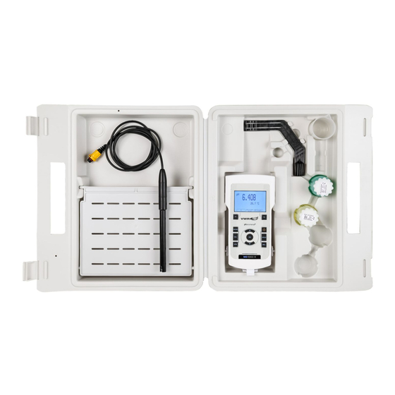
- Page 1 ® MD 8000 H Multi Parameter Meter OPERATING MANUAL European Catalogue Number(s): PH SET: 665-0494 COND SET: 665-0495 DI.OX SET: 665-0496 Version: Issued: November 28, 2018 7:51 am ba77219e01 11/2018...
- Page 2 MD 8000 H Legal Address of Manufacturer: VWR International bvba Researchpark Haasrode 2020 Geldenaaksebaan 464 B-3001 Leuven +32 16 385011 http://be.vwr.com Country of origin: Germany. ba77219e01 11/2018...
-
Page 3: Table Of Contents
MD 8000 H meter ........ - Page 4 MD 8000 H pH value......... . 25 Measuring .
- Page 5 MD 8000 H 10.2.5 Calibration data......59 11 Settings ......... . 61 11.1 pH measurement settings .
- Page 6 16 Firmware update ........87 16.1 Firmware update for the meter MD 8000 H ....87 16.2 Firmware update for IDP sensors .
-
Page 7: Safety
MD 8000 H Safety Safety Safety information 1.1.1 Safety information in the operating manual This operating manual provides important information on the safe operation of the meter. Read this operating manual thoroughly and make yourself familiar with the meter before putting it into operation or working with it. The operating manual must be kept in the vicinity of the meter so you can always find the infor- mation you need. -
Page 8: Safe Operation
Safety MD 8000 H Safe operation 1.2.1 Authorized use The authorized use of the meter consists exclusively of the measurement of the pH, ORP, conductivity and dissolved oxygen in a laboratory environment. Only the operation and running of the meter according to the instructions and technical specifications given in this operating manual is authorized (see section 3 T , page 11). -
Page 9: Overview
1 Keypad 2 Display 3 Connectors Sensors A measuring system ready to measure consists of the MD 8000 H meter and a suitable sensor. Suitable sensors are IDP pH sensors, IDP ORP sensors, IDP conductivity sensors and IDP D.O. sensors. -
Page 10: Automatic Sensor Recognition
to hide menus automatically that do not concern this sensor To be able to use the automatic sensor recognition, a meter that supports the automatic sensor recognition (e.g. MD 8000 H) and a digital IDP sensor are required. In digital IDP sensors, sensor data are stored that clearly identify the sensor. -
Page 11: Technical Data
MD 8000 H Technical data Technical data Measuring ranges, resolution, accuracy Measuring ranges, Variable Measuring range Accuracy accuracy Air pressure (abso- 300 ... 1100 mbar ± 4 mbar lute)* Available only if a D.O. sensor is connected Further data are given in the documentation of your sensor. - Page 12 Technical data MD 8000 H USB interface (device) Type USB 1.1 USB-B (Device), PC Baud rate Adjustable: 1200, 2400, 4800, 9600, 19200 Baud Data bits Stop bits Parity None Handshake RTS/CTS Cable length max. 3 m (9.843 feet) Guidelines EC directive 2004/108/EC...
-
Page 13: Commissioning
– Comprehensive operating manual (6 languages) – Software MultiLab Importer Power supply The MD 8000 H is supplied with power in the following ways: Battery operation (4 batteries, 1.5 V Mignon type AA) USB operation via a connected USB-B cable... -
Page 14: Inserting The Batteries
Commissioning MD 8000 H 4.3.1 Inserting the batteries You can operate the meter either with normal batteries or with rechargeable batteries (Ni-MH). In order to charge the batteries, an external charging device is required. 1 Screws 2 Battery compartment Unscrew the screws (1) on the underside of the meter. -
Page 15: Operation
MD 8000 H Operation Operation General operating principles 5.1.1 Keypad In this operating manual, keys are indicated by brackets <..> . <OK> The key symbol (e.g. ) generally indicates a short keystroke (press and release) in this operating manual. A long keystroke (press and keep depressed for approx. 2 sec) is indicated by <OK... -
Page 16: Display
Operation MD 8000 H 5.1.2 Display Example (pH): AutoCal TEC HOLD AR 01.11.2018 USB output 08:00 1 Status information (sensor) 2 Measured value 3 Measured parameter 4 Sensor symbol (calibration evaluation, calibration interval) 5 Measured temperature (with unit) 6 Status information (meter) 7 Softkeys and date + time 5.1.3 Status information (meter) -
Page 17: Socket Field
Only connect sensors to the meter that cannot return any volt- ages or currents that are not allowed (> SELV and > current circuit with current limiting). VWR-IDP sensors meet these requirements. 5.1.5 Sensor info You can display the current sensor data and sensor settings of a connected sensor at any time. -
Page 18: Switching On The Meter
Operation MD 8000 H 7.007 25.0 °C IDP 711 01.11.2018 More B09250001 08:00 <F1> Display further sensor data (settings) with /[More]. IDP 711 B092500013 pH resolution 0.001 mV resolution Buffer Calibration interval Unit for slope mV/pH Software version V1.00 01.11.2018... -
Page 19: Switching Off The Meter
MD 8000 H Operation Switching off the meter <On/Off> Switch the meter off with Navigation 5.4.1 Operating modes Operating Explanation mode Measuring The measurement data of the connected sensor are shown in the measured value display Calibration The course of a calibration with calibration information, func-... - Page 20 Operation MD 8000 H System General Interface Clock function Service information Reset 01.11.2018 Back 08:00 Settings Settings are indicated by a colon. The current setting is displayed on the <OK> right-hand side. The setting mode is opened with . Subsequently, the <...
-
Page 21: Navigation Example 1:Setting The Language
MD 8000 H Operation Messages Information is marked by the [ ] symbol. It cannot be selected. Example: Calibration record Calibration data storage Buffer: Single-point calibration: Calibration interval: Unit for slope: mV/pH ] 2.00 4.00 7.00 10.00 (25 °C) 01.11.2018... - Page 22 Operation MD 8000 H Storage & config System Data storage 01.11.2018 Back 08:00 < >< > Select the System submenu with The current selection is displayed with a frame. <OK> Open the System submenu with System General Interface...
-
Page 23: Example 2 On Navigation: Setting The Date And Time
MD 8000 H Operation General Language: Deutsch Audio signal: Illumination: Contrast: 50 % Shutoff time: Temperature unit: °C 01.11.2018 Back 08:00 < >< > Select the required language with <OK> Confirm the setting with The meter switches to the measuring mode. - Page 24 Operation MD 8000 H Clock function Date format: dd.mm.yy Date: 01.11.2018 Time: 14:53:40 01.11.2018 Back 08:00 < >< > <OK> Select and confirm the Time menu with The hours are highlighted. < >< > <OK> Change and confirm the setting with ...
-
Page 25: Ph Value
MD 8000 H pH value pH value Measuring 6.1.1 Measuring the pH value NOTE When connecting a grounded PC/printer, measurements cannot be performed in grounded media as the values would be incorrect. The USB interface is not galvanically isolated. Connect the IDP pH sensor to the meter. -
Page 26: Measuring The Temperature
MD 8000 H You can terminate the Stability control function and the HOLD func- <HOLD> <MODE> tion with at any time. <OK> Using , activate the Stability control function manually. The [AR] status indicator appears while the measured value is assessed as not stable. -
Page 27: Ph Calibration
MD 8000 H pH value mode: Temperature Resolution of Temp. measurement sensor the temp. dis- play 0.1 °C Automatic with temperature sensor 1 °C Manual pH calibration 6.2.1 Why calibrate? pH electrodes age. This changes the zero point (asymmetry) and slope of the pH electrode. - Page 28 MD 8000 H Buffer -180.0 24.8 °C AutoCal TEC 01.11.2018 08:00 Thoroughly rinse the sensor with deionized water. Immerse the sensor in the first buffer solution. <OK> Start the measurement with The measured value is checked for stability (stability control).
- Page 29 MD 8000 H pH value Immerse the pH sensor in buffer solution 2. When measuring without temperature sensor: < >< > Enter the temperature of the buffer with <OK> Start the measurement with The measured value is checked for stability (stability control).
-
Page 30: Carrying Out A Manual Calibration (Anycal)
MD 8000 H 4.00 Buffer 180.0 24.8 °C AutoCal TEC 01.11.2018 08:00 Wait for the measurement with stability control to be completed or ter- minate the stability control and take over the calibration value with <OK> The calibration display for the next buffer appears (voltage display). - Page 31 MD 8000 H pH value Buffer 24.8 °C AnyCal 01.11.2018 08:00 Thoroughly rinse the sensor with deionized water. Immerse the pH sensor in buffer solution 1. <OK> Start the measurement with The measured value is checked for stability (stability control).
- Page 32 MD 8000 H Set the nominal buffer value for the measured temperature with < >< > <OK> Accept the calibration value with The calibration display for the next buffer appears (voltage display). If necessary, finish the calibration procedure as a single-point calibration <MODE>...
- Page 33 MD 8000 H pH value If necessary, finish the calibration procedure as a two-point calibration <MODE> with The calibration record is displayed. Continuing with Thoroughly rinse the sensor with deionized water. three- to five-point calibration Immerse the sensor in the next buffer solution.
-
Page 34: Calibration Points
MD 8000 H 6.2.5 Calibration points Calibration can be performed using one to five buffer solutions in any order (single-point to five-point calibration). The meter determines the following values and calculates the calibration line as follows: Calibration Determined... - Page 35 MD 8000 H pH value Menu item Setting/ Explanation function Calibration / Displays the calibration records. Calibration data stor- Further options: age / Display Scroll through the calibration < >< > records with Output the displayed calibration <F2>...
- Page 36 MD 8000 H Display Calibration Zero point Slope [mV/pH] record [mV] Error Error <-30 <-62.0 >+30 > -50,0 Error elimination (see section 15 W ..., page 83) HAT TO DO IF Calibration record MD 8000 H (USB output) Ser.
-
Page 37: Orp
MD 8000 H Measuring 7.1.1 Measuring the ORP NOTE When connecting a grounded PC/printer, measurements cannot be performed in grounded media as the values would be incorrect. The USB interface is not galvanically isolated. IDP ORP sensors are not calibrated. However, you can check IDP ORP sensors using a test solution. -
Page 38: Measuring The Temperature
MD 8000 H , page 69) in the System menu. CONTROL <HOLD> Freeze the measured value with The [HOLD] status indicator is displayed. The HOLD function is active. You can terminate the Stability control function and the HOLD func- <HOLD>... -
Page 39: Orp Calibration
MD 8000 H to measure and enter the temperature of the sample. The measuring instrument recognizes whether a suitable sensor is connected and automatically switches on the temperature measurement. The display of the temperature indicates the active temperature measuring mode:... -
Page 40: Dissolved Oxygen
Dissolved oxygen MD 8000 H Dissolved oxygen Measuring 8.1.1 Measuring D.O. Connect the D.O. sensor to the meter. The D.O. measuring screen is displayed. <MODE> If necessary, select the measured parameter with Check or calibrate the meter with the sensor. - Page 41 MD 8000 H Dissolved oxygen Air pressure The integrated air pressure sensor of the MD 8000 H measures the current air correction pressure. During calibration, the air pressure correction function is automati- (Saturation, local cally activated. While the parameter oxygen saturation [%] is displayed, the air function) pressure correction is applied if the Saturation, local function is active.
-
Page 42: Measuring The Temperature
Dissolved oxygen MD 8000 H You can prematurely terminate the Stability control function manu- <OK> ally with at any time. If the Stability control function is pre- maturely terminated, the current measurement data are output to the interface without the AutoRead info. -
Page 43: Calibration Procedures
MD 8000 H Dissolved oxygen 8.2.3 Calibration procedures The MD 8000 H provides 2 calibration procedures: Calibration in water vapor-saturated air. Calibration via a comparison measurement (e.g. Winkler titration according to DIN EN 25813 or ISO 5813). At the same time, the relative slope is adapted to the comparison measurement by a correction factor. -
Page 44: Calibrating With Comparison Meas. (E.g. Winkler Titration)
Dissolved oxygen MD 8000 H <OK> Start the measurement with The measured value is checked for stability (stability control). The [AR] status indicator is displayed. The measured parameter flashes. Wait for the measurement with stability control to be finished (beep, [HOLD][AR] status indicator). -
Page 45: Zero Point Calibration
MD 8000 H Dissolved oxygen DO Adjust 7.92 mg/l 20.3°C Compare 01.11.2018 08:00 < > < > Using , set the correction factor to adjust the displayed mea- sured value to the nominal value (value of the comparison measure- <OK>... -
Page 46: Calibration Data
Dissolved oxygen MD 8000 H DO Zero 25.1°C 01.11.2018 08:00 <OK> Start the measurement with The measured value is checked for stability (stability control). The [AR] status indicator is displayed. The measured parameter flashes. Wait for the measurement with stability control to be finished (beep, [HOLD][AR] status indicator). - Page 47 MD 8000 H Dissolved oxygen Menu item Setting/ Explanation function Calibration / Displays the calibration records. Calibration data stor- Further options: age / Display Scroll through the calibration < >< > records with Output the displayed calibra- tion record to the interface with <F2>...
-
Page 48: Conductivity
Conductivity MD 8000 H Conductivity Measuring 9.1.1 Measuring the conductivity NOTE When connecting a grounded PC/printer, measurements cannot be performed in grounded media as the values would be incorrect. The USB interface is not galvanically isolated. Connect the conductivity sensor to the meter. - Page 49 MD 8000 H Conductivity You can start the Stability control manually at any time, irrespective of the set- ting for automatic Stability control (see section 11.6.3 A UTOMATIC TABILITY , page 69) in the System menu. CONTROL <HOLD> Freeze the measured value with The [HOLD] status indicator is displayed.
-
Page 50: Measuring The Temperature
Conductivity MD 8000 H 9.1.2 Measuring the temperature For reproducible conductivity measurements, it is essential to measure the temperature of the test sample. IDP sensors measure the temperature with a temperature sensor integrated in the IDP sensor. Temperature compensation The calculation of the temperature compensation is based on the preset refer- ence temperature, 20 °C or 25 °C. -
Page 51: When To Calibrate
MD 8000 H Conductivity of the cell constant and stores this value in the meter. Thus, you should calibrate at regular intervals. 9.3.2 When to calibrate? After connecting a sensor Routinely within the framework of the company quality assurance ... -
Page 52: Calibration Data
Conductivity MD 8000 H <OK> Start the measurement with The measured value is checked for stability (stability control). The [AR] status indicator is displayed. The measured parameter flashes. Wait for the end of the measurement with stability control ([HOLD][AR]) status indicator or <OK>... - Page 53 MD 8000 H Conductivity Calibration evalua- After calibration, the meter automatically evaluates the current status of the cal- tion ibration. The evaluation appears on the display and in the calibration record. Display Calibration record Cell constant [cm Within the range 0.450 ...
-
Page 54: Turbidity Measurement (Visoturb ® 900-P)
This facilitates interference-free measurements also in the following cases: Measurement in grounded test samples Measurement with several sensors connected to one MD 8000 H in one test sample Preparatory activi- Perform the following preparatory activities when you want to measure: ties ... - Page 55 ® MD 8000 H Turbidity measurement (VisoTurb 900-P) 7.92 01.02.2014 USB output 08:00 <M> Selecting the You can switch between the following displays with displayed Turbidity [FNU] measured parameter Turbidity [NTU] Freezes the mea- With the HOLD function, you can freeze the current measured value. The dis- sured value (HOLD played measured value stops changing until you switch the HOLD function off.
-
Page 56: Calibration
® Turbidity measurement (VisoTurb 900-P) MD 8000 H <OK> Using , activate the Stability control function manually. The [AR] status indicator appears while the measured value is assessed as not stable. A progress bar is displayed and the display of the measured parameter flashes. -
Page 57: Carry Out Calibration
® MD 8000 H Turbidity measurement (VisoTurb 900-P) be selected in the following order. Standard solution Range (FNU/NTU) 0.0 ... 1.0 5.0 ... 200.0 200.0 ... 4000.0 The turbidity expected in the measurement dictates the number and selection of the standards. Calibration has to be carried out for the range with the highest turbidity to be expected and for all lower ranges. - Page 58 ® Turbidity measurement (VisoTurb 900-P) MD 8000 H Standard 000.0 FNU 01.07.2011 08:00 Thoroughly rinse the turbidity sensor with distilled water and dry it with a lint-free cloth. Immerse the turbidity sensor in the test sample at an angle.
-
Page 59: Calibration Data
® MD 8000 H Turbidity measurement (VisoTurb 900-P) Standard 124.0 1010.0 FNU 01.07.2011 08:00 If necessary, terminate the calibration as a two-point calibration with <MODE> The new calibration values are displayed. Continue with three-point calibration. Continuing with Repeat the steps 11 to 15 with the third standard solution. The new calibration three-point calibra- values are displayed after the last calibration step was completed. - Page 60 ® Turbidity measurement (VisoTurb 900-P) MD 8000 H Menu item Setting/ Explanation function Calibration / Displays the calibration record. Calibration data storage / Display Further options: Scroll through the calibration < > >< records with Output the displayed calibration record to the interface with <PRT>...
-
Page 61: Settings
MD 8000 H Settings Settings 11.1 pH measurement settings 11.1.1 Settings for pH measurements Settings The settings are made in the menu for calibration and measurement settings of the pH/ORP measurement. To open the settings, display the required mea- <OK>... -
Page 62: Buffer Sets For Calibration
Settings MD 8000 H 11.1.2 Buffer sets for calibration You can use the buffer sets quoted in the table for an automatic calibration. The pH values are valid for the specified temperature values. The temperature dependence of the pH values is taken into consideration during the calibration. -
Page 63: Calibration Interval
MD 8000 H Settings 11.1.3 Calibration interval The calibration evaluation is displayed as a sensor symbol. To ensure the high measuring accuracy of the measuring system, calibrate after the calibration interval has expired. Setting the calibra- The calibration interval is set to 7 days in the factory. - Page 64 Settings MD 8000 H <MODE> tings, switch to the measured value display with Default settings are printed in bold. Menu item Possible Explanation setting Calibration / Displays the calibration record of Calibration record the last calibration. Calibration / Displays the last calibration Calibration data records.
-
Page 65: Enter Cap Coefficients
MD 8000 H Settings Menu item Possible Explanation setting Saturation, local Saturation, local is a procedure that takes the local air pressure into account for each saturation mea- surement. For details, see section 11.3.3 S , page 65. URATION LOCAL... - Page 66 Settings MD 8000 H <M> switch to the measured value display with Default settings are printed in bold. Setting menu Menu item Possible Explanation setting Calibration / Displays the calibration record of Calibration record the last calibration. Calibration / Displays the last calibration Calibration data stor- records (max.
-
Page 67: Turb Measurement Settings
MD 8000 H Settings Menu item Possible Explanation setting Temp. comp. (TC) / 0.000 ... Coefficient of the linear tempera- Linear coeff. 2.000 ... ture compensation. 3.000 %/K This menu item is only available when the linear temperature compensation is set. -
Page 68: Sensor-Independent Settings
Settings MD 8000 H Menu item Possible Explanation setting Calibration / 1 ... 30 ... Calibration interval for the turbidity Calibration interval 999 d sensor (in days). The meter reminds you to calibrate regularly by the flashing sensor sym- bol in the measuring screen. -
Page 69: Data Storage
TEM SETTINGS 11.6.2 Data storage This menu contains all functions to display, edit and erase stored measured values. Detailed information on the memory functions of the MD 8000 H are given in section 12 D , page 73. ATA STORAGE 11.6.3 Automatic Stability control... -
Page 70: Automatic Switch-Off Function
Settings MD 8000 H 11.6.4 Automatic switch-off function The instrument has an automatic switch-off function in order to save the batteries (see section 11.6.1 S , page 68). The automatic switchoff func- YSTEM tion switches off the meter if no key is pressed for an adjustable period. - Page 71 MD 8000 H Settings Setting Default settings Man. temperature 25 °C Single-point calibration The sensor settings are reset under the Reset menu item in the menu for cali- bration and measurement settings. To open the settings, display the required <OK>...
-
Page 72: Resetting The System Settings
Settings MD 8000 H Setting Default settings Cell constant (c) Depending on the connected measur- ing cell: 0.475 cm (calibrated) 0.475 cm (set) Temperature compensation Reference temperature 25 °C Temperature coefficient (TC) of 2.000 %/K the linear temperature compensa- tion TDS multiplier 1.00... -
Page 73: Data Storage
MD 8000 H Data storage Data storage You can transmit measured values (datasets) to the data storage: Manual data storage (see section 12.1 M , page 73) ANUAL DATA STORAGE Automatic data storage at intervals (see section 12.2 A... -
Page 74: Automatic Data Storage At Intervals
Data storage MD 8000 H 12.2 Automatic data storage at intervals The storage interval (Interval) determines the time interval between automatic data storage processes. Each data storage process transmits the current data- set to the USB interface. Configuring the <STR >... - Page 75 MD 8000 H Data storage < >< > Starting the auto- To start the automatic data storage function, select continue with <OK> matic storing func- and confirm with . The meter switches to the measured value display. tion 7.007...
-
Page 76: Measurement Data Storage
Data storage MD 8000 H 12.3 Measurement data storage 12.3.1 Editing the measured value data storage The contents of the manual or automatic measurement data storage can be shown on the display. Each of the measurement data storages has a function to erase the entire contents. -
Page 77: Erasing The Measurement Data Storage
MD 8000 H Data storage Display presentation Manual data storage 3 of 64 of a dataset 01.11.2018 07:43:33 ID number: 1 IDP 711 B092500013 pH 7.000 24.8 °C AR Sensor: +++ 01.11.2018 Back USB output 08:00 Representation of a 01.11.2018 07:43:33... -
Page 78: Storage Locations
- 4 levels (+++, ++, +, -, or no evaluation) 12.3.4 Storage locations The MD 8000 H meter has two measurement data storages. The measured values recorded either manually or automatic are stored separately in indi- vidual measurement data storages. -
Page 79: Transmitting Data (Usb Interface)
13.3 Connecting the PC / USB-B interface (USB Device) Connect the MD 8000 H to the PC via the USB-B interface. Installation of the System requirements of the PC for installation of the USB driver: USB driver on the ... -
Page 80: Options For Data Transmission To A Pc
Transmitting data (USB interface) MD 8000 H 13.4 Options for data transmission to a PC Via the USB-B interface you can transmit data to a PC. The following table shows which data are transmitted to the interface in which way:... -
Page 81: Maintenance, Cleaning, Disposal
MD 8000 H Maintenance, cleaning, disposal Maintenance, cleaning, disposal 14.1 Maintenance 14.1.1 General maintenance activities The only maintenance activity required is replacing the batteries. See the relevant operating manuals of the IDP sensors for instruc- tions on maintenance. 14.1.2 Replacing the batteries You can operate the meter either with normal batteries or with rechargeable batteries (Ni-MH). -
Page 82: Cleaning
Maintenance, cleaning, disposal MD 8000 H Set the date and time (see section 5.4.5 E XAMPLE ON NAVIGATION , page 23). TING THE DATE AND TIME Dispose of used batteries according to the local regulations of your country. End users within the European Union are obligated to return used batteries (even ecologically compatible ones) to a collection point set up for recycling purposes. -
Page 83: What To Do If
MD 8000 H What to do if... What to do if... 15.1 pH More information and instructions on cleaning and exchange of sensors are given in the documentation of your sensor. Error message The measured value is outside the measuring range. -
Page 84: Dissolved Oxygen
What to do if... MD 8000 H No stable measured Cause Remedy value IDP pH sensor: – Junction contaminated – Clean junction – Membrane contaminated – Clean membrane – pH sensor soiled – Clean the pH sensor Test sample: – pH value not stable –... -
Page 85: Conductivity
MD 8000 H What to do if... Cause Remedy – Measured value outside the – Use a suitable IDP D.O. sensor measuring range Error message, Cause Remedy Error – Sensor contaminated – Clean the sensor – Measured temperature value – Keep to the temperature range for... - Page 86 What to do if... MD 8000 H Display Cause Remedy – Batteries almost empty – Replace the batteries (see section 14.1 M , page 81) AINTENANCE Meter does not react Cause Remedy to keystroke – Operating condition undefined – Processor reset: <OK>...
-
Page 87: Firmware Update
a free USB interface (virtual COM port) on the PC the driver for the USB interface (on the enclosed CD-ROM) the USB cable (included in the scope of delivery of the MD 8000 H). Install the downloaded firmware update on a PC. -
Page 88: Firmware Update For Idp Sensors
a free USB interface (virtual COM port) on the PC the driver for the USB interface (on the enclosed CD-ROM) the USB cable (included in the scope of delivery of the MD 8000 H). Install the downloaded firmware update on a PC. -
Page 89: Glossary
MD 8000 H Glossary Glossary pH/ORP Asymmetry see zero point Electromotive force of The electromotive force U of the combination electrode is the measur- an electrode able electromotive force of an electrode in a solution. It equals the sum of all the galvanic voltages of the combination electrode. Its depen- dency on the pH results in the electrode function, which is characterized by the parameters, slope and zero point. - Page 90 Glossary MD 8000 H Salinity The absolute salinity S of seawater corresponds to the relationship of the mass of dissolved salts to the mass of the solution (in g/Kg). In prac- tice, this dimension cannot be measured directly. Therefore, the practi- cal salinity according to IOT is used for oceanographic monitoring.
- Page 91 MD 8000 H Glossary Calibration Comparing the value from a measuring system (e. g. the displayed value) to the correct value or a value that is regarded as correct. Often, this expression is also used when the measuring system is adjusted at the same time (see adjusting).
-
Page 92: Index
MD 8000 H Index Index Automatic switch-off function ... 70 Measured value display ....19 AutoRead ....41, 48, 55 Measurement accuracy . - Page 93 MD 8000 H Index Three-point calibration ISE ......59 pH ......29, 33 Transmitting data .
-
Page 94: Technical Service
Warranty VWR warrants that this product will be free from defects in material and workmanship for a period of three (3) years from date of delivery. If a defect is present, VWR will, at its option and cost, repair, replace, or refund the purchase price of this product to the customer, provided it is returned during the warranty period. - Page 96 Your Distributor Austria Germany Poland VWR International GmbH VWR International GmbH VWR International Sp. z o.o. Graumanngasse 7 Hilpertstraße 20a Limbowa 5 1150 Vienna D - 64295 Darmstadt 80-175 Gdansk Tel.: +43 01 97 002 0 Freecall: 0800 702 00 07 Tel.: +48 058 32 38 200...
Need help?
Do you have a question about the MD 8000 H and is the answer not in the manual?
Questions and answers