
Subscribe to Our Youtube Channel
Related Manuals for VWR 665-0309


Summary of Contents for VWR 665-0309
- Page 1 Operating manual ® MU 6100 L - Multi Meter EU cat. no NA cat. no MU 6100 L S1 665-0309 76460-494 MU 6100 L S2 665-0310 76460-496 ba77076e06 05/2021...
- Page 2 MU 6100 L Legal Address of Manufacturer: Europe United States VWR International BV VWR International LLC Researchpark Haasrode 2020 100 Matsonford Rd Geldenaaksebaan 464 Radnor, PA 19087 B-3001 Leuven +1 800-932-5000 +32 16 385011 www.vwr.com http://be.vwr.com Importer to UK: VWR International Ltd...
-
Page 3: Table Of Contents
MU 6100 L Contents MU 6100 L - Contents Safety ........7 Safety information . - Page 4 Contents MU 6100 L 5.4.2 Measured value display ....22 5.4.3 Menus and dialogs ..... . . 22 5.4.4 Elements in menus and dialogs .
- Page 5 MU 6100 L Contents 9.2.3 Calibration procedure..... 51 9.2.4 Calibration in water vapor-saturated air (air calibration vessel) ....51 9.2.5 Calibrating with a comparison measurement (OxiComp) .
- Page 6 Contents MU 6100 L 13 Transmitting data (USB interface) ....81 13.1 Options for data transmission ..... 81 13.2 Connecting a PC .
-
Page 7: Safety
MU 6100 L Safety Safety Safety information 1.1.1 Safety information in the operating manual This operating manual provides important information on the safe operation of the meter. Read this operating manual thoroughly and make yourself familiar with the meter before putting it into operation or working with it. The operating manual must be kept in the vicinity of the meter so you can always find the infor- mation you need. -
Page 8: Safe Operation
Safety MU 6100 L Safe operation 1.2.1 Authorized use This meter is authorized exclusively for pH, ISE, ORP, dissolved oxygen and conductivity measurements in a laboratory environment. Only the operation and running of the meter according to the instructions and technical specifications given in this operating manual is authorized (see section 3 T , page 10). -
Page 9: Overview
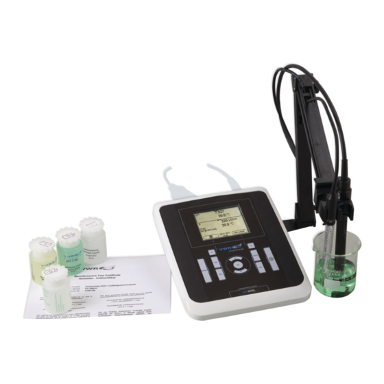
MU 6100 L Overview Overview MU 6100 L meter The MU 6100 L meter enables you to perform measurements (pH, U, conduc- tivity, dissolved oxygen) ) quickly and reliably. The MU 6100 L provides the maximum degree of operating comfort, reliability and measuring certainty for all applications. -
Page 10: Technical Data
Technical data MU 6100 L Technical data Measuring ranges, resolution, accuracy 3.1.1 pH/ORP Measuring ranges, Variable Measuring range Resolution resolution -2.0 ... +20.0 -2.00 ... +20.00 0.01 - 2.000 ... + 19.999 0.001 U [mV] -2500 ... +2500 -1200.0 ... +1200. T [°C] -5.0 ... -
Page 11: Oxi
MU 6100 L Technical data 3.1.2 Oxi Measuring ranges, Variable Measuring range Resolution resolution Concentration [mg/l] 0 ... 20.00 (0 ... 20.0) 0.01 (0.1) (depending on the 20.0 ... 90.0 0.1 (1) sensor) (20 ... 90) Saturation [%] 0 ... 200.0 (0 ... 600) 0.1 (1) 0 ... -
Page 12: Cond
Technical data MU 6100 L 3.1.3 Cond Measuring ranges, Variable Measuring range Resolution resolution ϰ [µS/cm] 0.000 ... 1.999* 0.001 (depending on the sen- 0.00 ... 19.99** 0.01 sor) 0.0 ... 199.9 200 ... 1999 ϰ [mS/cm] 2.00 ... 19.99 0.01 20.0 ... -
Page 13: General Data
MU 6100 L Technical data Accuracy (± 1 digit) Variable Accuracy Temperature of the test sample ϰ and ρ / temperature compensation None (Off) ± 0.5 % Nonlinear (nLF) ± 0.5 % 0 °C ... +35 °C according to EN 27 888 ±... - Page 14 Technical data MU 6100 L Power Batteries 4 x 1.5 V alkali-manganese batteries, type supply Rechargeable batter- 4 x 1.2 V NiMH rechargeable batteries, type AA (no charging function) Operational life Up to 1000 h without / 150 h with illumination Power pack Input: 100 ...
-
Page 15: Commissioning
MU 6100 L Commissioning Commissioning Scope of delivery MeterMU 6100 L 4 batteries 1.5 V Mignon type AA Power pack Stand Stand holder Short instructions CD-ROM with – USB drivers – detailed operating manual –... -
Page 16: Inserting The Batteries
Commissioning MU 6100 L 4.3.1 Inserting the batteries 1 Battery compartment Open the battery compartment (1) on the underside of the meter. CAUTION Make sure that the poles of the batteries are positioned cor- rectly. ± The ± signs on the batteries must correspond to the signs in the battery compartment. -
Page 17: Stand
MU 6100 L Commissioning CAUTION Use original power packs only. Connect the plug of the power pack to the socket for the power pack on the MU 6100 L. Connect the original power pack to an easily accessible power outlet. 4.3.3 Stand The stand base can be mounted at the right side of the meter. -
Page 18: Operation
Operation MU 6100 L Operation General operating principles 5.1.1 Keypad In this operating manual, keys are indicated by brackets <..> . <OK> The key symbol (e.g. ) generally indicates a short keystroke (under 2 sec) in this operating manual. A long keystroke (approx. 2 sec) is indicated <OK >... -
Page 19: Display
MU 6100 L Operation 5.1.2 Display 6.093 25.0 °C AutoCal TEC HOLD AR 15.03.2014 Menu 08:00 1 Status information (sensor) 2 Measured value (with unit) 3 Measured parameter 4 Channel display: Plug position of the sensor 5 Sensor symbol (calibration evaluation, calibration interval) 6 Measured temperature (with unit) 7 Status information (meter) 8 Softkeys and date + time... -
Page 20: Connectors
Operation MU 6100 L 5.1.4 Connectors 1 pH electrode 2 Reference electrode / temperature sensor 3 Reference electrode / temperature sensor 4 D.O. sensor or conductivity measuring cell 5 Mini USB-B interface 6 Power pack 7 Service interface CAUTION Only connect sensors to the meter that cannot return any volt- ages or currents that are not allowed (>... -
Page 21: Switching Off
MU 6100 L Operation Switching off <On/Off> Switch the printer off with Automatic shut-off The instrument has an automatic shut-off function in order to save the batteries function (see section 11.2.1 S , page 71). The automatic shut-off function switches YSTEM off the meter if no key is pressed for an adjustable period. -
Page 22: Measured Value Display
Operation MU 6100 L 5.4.2 Measured value display <OK> In the measured value display, open the setting menus with . The current functions of the softkeys are shown on the display. <OK> Use (short pressure) to open the menu for calibration and measure- ment settings for the displayed measured parameter. -
Page 23: Navigation Example 1:Setting The Language
MU 6100 L Operation General Language: Deutsch Beep: Illumination: Contrast: 50 % Switchoff time: Temperature unit: °C Stability control: 15.02.2014 Back 14:15 Functions Functions are designated by the name of the function. They are immediately <OK> carried out by confirming with Example: Display the Calibration record function. - Page 24 Operation MU 6100 L 6.949 25.0 °C 15.02.2014 Menu 14:15 <OK > Open the Storage & config menu with The instrument is in the setting mode. Storage & config System Data storage 15.02.2014 Back 14:15 < >< > Select the System submenu with ...
-
Page 25: Example 2 On Navigation: Setting The Date And Time
MU 6100 L Operation General Language: Deutsch Beep: Illumination: Contrast: 50 % Switchoff time: Temperature unit: °C Stability control: 15.02.2014 Back 14:15 <OK> Open the setting mode for the Language with General Language: Deutsch Beep: Illumination: Contrast: 50 % Switchoff time: Temperature unit: °C Stability control:... - Page 26 Operation MU 6100 L The date format can be switched from the display of day, month, year (dd.mm.yyyy) to the display of month, day, year (mm/dd/yyyy or mm.dd.yyyy). In the measured value display: <OK > Open the Storage & config menu with The instrument is in the setting mode.
-
Page 27: Channel Display
MU 6100 L Operation Channel display The MU 6100 L manages the connected sensors and displays which sensor is plugged to which connection. Channel display Display of the plug position for the respective parameter The filled bar indicates for 6.949 each connected sensor to which plug position of the 24.8 °C... -
Page 28: Ph Value
pH value MU 6100 L pH value Measuring 6.1.1 Measuring the pH value NOTE When connecting an grounded PC/printer, measurements cannot be performed in grounded media as the values would be incorrect. The USB interface is not galvanically isolated. To ensure the high measurement accuracy of the measuring sys- tem, always measure with a calibrated electrode (see section 6.2 , page 30). -
Page 29: Measuring The Temperature
MU 6100 L pH value within the monitored time interval. Measured Time interval Stability in the time interval parameter Δ : better than 0.01 pH pH value 15 seconds Δ : better than 0.5 °C Temperature 15 seconds The minimum duration until a measured value is assessed as stable is the monitored time interval. -
Page 30: Calibration
pH value MU 6100 L Calibration 6.2.1 Why calibrate? pH electrodes age. This changes the zero point (asymmetry) and slope of the pH electrode. As a result, an inexact measured value is displayed. Calibration determines and stores the current values of the zero point and slope of the electrode. - Page 31 MU 6100 L pH value Buffer -180.0 24.8 °C AutoCal TEC 15.02.2014 14:15 Thoroughly rinse the electrode with deionized water. Immerse the electrode in the first buffer solution. When measuring without temperature sensor: – Temper the buffer solution, or measure the current temperature. –...
- Page 32 pH value MU 6100 L When measuring without temperature sensor: – Temper the buffer solution, or measure the current temperature. – Enter the temperature value in the menu. <OK> Start the measurement with The measured value is checked for stability (stability control). The [AR] status indicator is displayed.
-
Page 33: Manual Calibration (Anycal)
MU 6100 L pH value Wait for the measurement with stability control to be completed or termi- <OK> nate the stability control and take over the calibration value with The calibration display for the next buffer appears (voltage display). <MODE> If necessary, use to finish calibration or <OK>... - Page 34 pH value MU 6100 L When measuring without temperature sensor: – Temper the buffer solution, or measure the current temperature. – Enter the temperature value in the menu. <OK> Start the measurement with The measured value is checked for stability (stability control). The [AR] status indicator is displayed.
- Page 35 MU 6100 L pH value Continuing with two- Thoroughly rinse the electrode with deionized water. point calibration Immerse the electrode in the second buffer solution. When measuring without temperature sensor: – Temper the buffer solution, or measure the current temperature. –...
-
Page 36: Calibration Points
pH value MU 6100 L Buffer 9.958 24.8 °C AnyCal 15.02.2014 14:15 Set the nominal buffer value for the measured temperature with < >< > <OK> Accept the set calibration value with The calibration display for the next buffer appears (voltage display). <MODE>... -
Page 37: Calibration Data
MU 6100 L pH value 6.2.6 Calibration data The calibration record is automatically transmitted to the interface after calibrating. Displays the calibra- The calibration record of the last calibration is to be found under the menu item, <OK> <CAL__> tion data / Calibration / Calibration record. - Page 38 pH value MU 6100 L record. Display Calibration Zero point Slope [mV/ record [mV] -15 ... +15 -60.5 ... -58.0 -20 ... <-15 >-58.0 ... -57.0 >+15 ... +20 -25 ... <-20 -61.0 ... <-60.5 >+20 ... +25 >-57.0 ... -56.0 -30 ...
-
Page 39: Orp Voltage
MU 6100 L ORP voltage ORP voltage Measuring 7.1.1 Measuring the ORP NOTE When connecting an grounded PC/printer, measurements cannot be performed in grounded media as the values would be incorrect. The USB interface is not galvanically isolated. Connect the ORP electrode to the meter. <MODE>... -
Page 40: Measuring The Temperature
ORP voltage MU 6100 L Freezes the mea- With the HOLD function, you can freeze the current measured value. The dis- sured value (HOLD played measured value stops changing until you switch the HOLD function off. function) <HOLD> Freeze the measured value with The [HOLD] status indicator is displayed. -
Page 41: Ion Concentration
MU 6100 L Ion concentration Ion concentration Measuring 8.1.1 Measuring the ion concentration NOTE When connecting an grounded PC/printer, measurements cannot be performed in grounded media as the values would be incorrect. The USB interface is not galvanically isolated. Incorrect calibration of ion sensitive electrodes will result in incor- rect measured values. -
Page 42: Measuring The Temperature
Ion concentration MU 6100 L page 72). Criteria The AutoRead criteria affect the reproducibility of the measured values. The following criteria can be adjusted: high: highest reproducibility medium: medium reproducibility low: lowest reproducibility Increasing reproducibility also causes the response time to increase until a measured value is evaluated as stable. -
Page 43: Calibration
MU 6100 L Ion concentration When measuring without temperature sensor: – Temper the test sample, or measure the current temperature. Calibration 8.2.1 Why calibrate? Ion-selective electrodes age and are temperature-dependent. This changes the slope. As a result, an inexact measured value is displayed. Calibration determines the calibration line of the electrode and stores this value in the meter. - Page 44 Ion concentration MU 6100 L Standard 24.8 °C 0.010 mg/l 15.02.2014 12:12 Thoroughly rinse the electrode with distilled water. Immerse the electrode in standard solution 1. When calibrating without temperature sensor: Measure the temperature of the standard solution using a thermom- eter.
- Page 45 MU 6100 L Ion concentration Standard 24.8 °C 0.020 mg/l 15.02.2014 12:12 Continuing with two- Thoroughly rinse the electrode with distilled water. point calibration Immerse the electrode in standard solution 2. When calibrating without temperature sensor: Measure the temperature of the standard solution using a thermom- eter.
-
Page 46: Calibration Standards
Ion concentration MU 6100 L <OK> Press to continue with three-point calibration. Finish the calibration procedure as a two-point calibration with <MODE> The new calibration values are displayed. Continuing with Repeat the steps 12 to 17 in the same way with the third and further standard three- to seven-point solutions as necessary. - Page 47 MU 6100 L Ion concentration Subsequently, you can transmit the displayed calibration data to the interface, <F2> e.g. to a PC, with the /[USB output] key. <OK> Displaying the cali- The calibration records of the last calibrations are available in the menu, bration data memory / Calibration / Calibration data storage.
- Page 48 Ion concentration MU 6100 L ba77076e06 05/2021...
-
Page 49: Dissolved Oxygen
MU 6100 L Dissolved oxygen Dissolved oxygen Measuring 9.1.1 Measuring D.O. NOTE When connecting an grounded PC/printer, measurements cannot be performed in grounded media as the values would be incorrect. The USB interface is not galvanically isolated. Connect the D.O. sensor to the meter. The D.O. -
Page 50: Measuring The Temperature
Dissolved oxygen MU 6100 L page 72). Criteria for a stable The Stability control function checks whether the measured values are stable measured value within the monitored time interval. Measured parameter Time interval Stability in the time interval Δ : better than 0.05 mg/l D.O. -
Page 51: Calibration
MU 6100 L Dissolved oxygen Calibration 9.2.1 Why calibrate? D.O. sensors age. This changes the slope of the D.O. sensor. Calibration deter- mines the current slope of the sensor and stores this value in the instrument. 9.2.2 When to calibrate? ... -
Page 52: Calibrating With A Comparison Measurement
Dissolved oxygen MU 6100 L 0.88 25.1 °C OxiCal 15.02.2014 08:00 <OK> Start the measurement with The measured value is checked for stability (stability control). The [AR] status indicator is displayed. A progress bar is displayed and the display of the measured parameter flashes. Wait for the end of the measurement with stability control or accept the <OK>... - Page 53 MU 6100 L Dissolved oxygen <OK> Start the measurement with The measured value is checked for stability (stability control). The [AR] status indicator is displayed. The measured parameter flashes. Wait for the end of the measurement with stability control or accept the <OK>...
-
Page 54: Calibration Data
Dissolved oxygen MU 6100 L 9.2.6 Calibration data The calibration record is automatically transmitted to the interface after calibrating. Displays the calibra- The calibration record of the last calibration is to be found under the menu item, <OK> <CAL__> tion data / Calibration / / Calibration record. - Page 55 MU 6100 L Dissolved oxygen Display Calibration Relative slope record S = 0.8 ... 1.25 S = 0.7 ... 0.8 S = 0.6 ... 0.7 S < 0.6 or S > 1.25 Error Error Error elimination (see section 15 ..., page 90) HAT TO DO IF Calibration record MU 6100 L...
-
Page 56: Conductivity
Conductivity MU 6100 L Conductivity 10.1 Measuring 10.1.1 Measuring the conductivity NOTE When connecting an grounded PC/printer, measurements cannot be performed in grounded media as the values would be incorrect. The USB interface is not galvanically isolated. Connect the conductivity measuring cell to the measuring instrument. The conductivity measuring screen is displayed. -
Page 57: Measuring The Temperature
MU 6100 L Conductivity The factor to calculate the total dissolved solids is set to 1.00 in the factory. You can adjust this factor to meet your requirements in the range 0.40 ... 1.00. The factor is set in the Measurement menu for the parameter, TDS. -
Page 58: Calibration
Conductivity MU 6100 L 10.2 Calibration 10.2.1 Why calibrate? Aging slightly changes the cell constant, e.g. due to coatings. As a result, an inexact measured value is displayed. The original characteristics of the cell can often be restored by cleaning the cell. Calibration determines the current value of the cell constant and stores this value in the meter. -
Page 59: Calibration Data
MU 6100 L Conductivity ϰ 0.839 1/cm 25.1 °C 15.02.2014 08:00 Immerse the conductivity measuring cell in the control standard solu- tion, 0.01 mol/l KCI. <OK> Start the measurement with The [AR] status indicator is displayed. A progress bar is displayed and the display of the measured parameter flashes. - Page 60 Conductivity MU 6100 L Menu item Setting/func- Explanation tion Calibration / Displays the calibration record. Calibration data stor- age / Display Further options: Scroll through the calibration < >< > records with Output the displayed calibra- Data storage / tion record to the interface with Calibration data stor-...
-
Page 61: Settings
MU 6100 L Settings Settings 11.1 Measurement settings 11.1.1 Settings for pH measurements The settings for pH measurements are made in the menu for calibration and measurement settings of the pH/ORP measurement. To open the settings, dis- play the required measured parameter in the measured value display and <OK>... -
Page 62: Buffer Sets For Calibration
Settings MU 6100 L Menu item Possible set- Explanation ting Calibration / Entry of the serial number of the connected sensor. Serial number (sen- The serial number is output in the sor) calibration record. Change the contents of the high- <... - Page 63 MU 6100 L Settings Buffer set * pH values TEC EU 2.00 20 °C Technical buffers EU 4.00 7.00 10.00 TEC US Technical buffers US AnyCal NIST/DIN 1.679 25 °C DIN buffers according to DIN 4.006 19266 and NIST Traceable 6.865 Buffers 9.180...
-
Page 64: Calibration Interval
Settings MU 6100 L 11.1.3 Calibration interval The calibration evaluation is displayed as a sensor symbol. The sensor symbol flashes after the adjusted calibration interval has expired. It is still possible to measure. To ensure the high measuring accuracy of the measuring system, calibrate after the calibration interval has expired. -
Page 65: Settings For D.o. Sensors
MU 6100 L Settings 11.1.5 Settings for D.O. sensors The settings are available in the menu for measurement and calibration set- tings. To open the settings, display the required measured parameter in the <OK> measured value display and press the key. -
Page 66: Calibration Interval
Settings MU 6100 L Menu item Possible Explanation setting Calibration / Enables to adjust the measured value with the aid of a comparison Comparison meas. measurement, e.g. Winkler titration. For details, see section 9.2 C , page 51. BRATION Manual salt content correction for Sal correction concentration measurements. -
Page 67: Settings For Conductivity Measuring Cells
MU 6100 L Settings 11.1.7 Settings for conductivity measuring cells The settings are made in the Measurement menu for the measured parameter, conductivity. To open the settings, display the required measured parameter in <OK> the measured value display and press the key. - Page 68 Settings MU 6100 L Menu item Possible Explanation setting Measurement / Measuring cell used Measuring cell / Measuring cells whose cell constant Type is determined by calibration in the KCL control standard solution. Calibration ranges: 0.450 ... 0.500 cm 0.800 ... 0.880 cm The currently valid cell constant is displayed in the status line.
-
Page 69: Calibration Interval
MU 6100 L Settings Menu item Possible Explanation setting Measurement / Reference temperature 20 °C Temp. comp. (TC) 25 °C /Reference temp. This setting is only available for the ϰ ρ measured parameters, Measurement / Multiplier for TDS value 0.40 ... 1.00 TDS factor Resets all sensor settings to the deliv- Reset... -
Page 70: Setting The Tds Factor
Settings MU 6100 L The reference temperature and temperature compensation are set in the Measurement menu for the parameter, conductivity (see sec- tion 11.1.7 S , page ETTINGS FOR CONDUCTIVITY MEASURING CELLS 67). Application tips Set the temperature compensation suitable for your test sample: Test sample Temperature compensation Display... -
Page 71: Sensor-Independent Settings
MU 6100 L Settings 11.2 Sensor-independent settings 11.2.1 System <OK > To open the Storage & config menu, press the key in the measured value display. After completing the settings, switch to the measured value dis- <MODE> play with Default settings are printed in bold. Menu item Possible Explanation... -
Page 72: Data Storage
Settings MU 6100 L Menu item Possible Explanation setting System / Clock Time and date settings (see Date format section 5.4.6 E Datum XAMPLE Time NAVIGATION ETTING THE DATE , page 25) AND TIME System / Service infor- Hardware version and software version of the meter are dis- mation played. - Page 73 MU 6100 L Settings with the Reset function: Setting Default settings Buffer Calibration interval mV/pH Unit for slope Measured parameter Resolution pH 0.001 Resolution mV Asymmetry 0 mV Slope -59.2 mV 25 °C Man. temperature One point calibration The sensor settings are reset under the Reset menu item in the menu for cali- bration and measurement settings.
-
Page 74: Resetting The System Settings
Settings MU 6100 L settings with the Reset function: Setting Default settings 150 d Kal.-Intervall ϰ Measured parameter 0.475 cm or 0.840 cm Cell constant (C) (nominal cell constant of the conduc- (calibrated) tivity measuring cell last calibrated) 0.840 1/cm Cell constant (C) (set) Temperature compensation... -
Page 75: Data Memory
MU 6100 L Data memory Data memory You can transmit measured values (datasets) to the data memory: Manual data memory (see section 12.1 M , page 75) ANUAL STORAGE Automatic storage at intervals (see section 12.2 A UTOMATIC DATA STORAGE , page 76) AT INTERVALS With each data storage process, the current datasets of the sen-... -
Page 76: Automatic Data Storage At Intervals
Data memory MU 6100 L If the memory is full The following window appears if all 200 storage locations are occupied: Warning Data storage full. Erase? 15.02.2014 Back 14:15 You have the following options: To erase the entire memory, confirm Yes. ... - Page 77 MU 6100 L Data memory Settings You can configure the automatic data storing function with the following settings: Menu item Possible set- Explanation ting ID number for the dataset series. ID number 1 ... 10000 Storing interval. Interval 1 s, 5 s, 10 s, 30 s, 1 min, The lower limit of the storing inter- 5 min,...
-
Page 78: Measurement Data Memory
Data memory MU 6100 L saving mode switches off functions of the meter that are not required for the automatic storage of measurement data (such as the display). By pressing any key the energy saving mode is switched off again. Terminating the Proceed as follows to switch off the automatic data storing function before the automatic memory... - Page 79 MU 6100 L Data memory Settings Menu item Setting/ Explanation function Data storage / Displays all measurement datasets page by page. Manual data storage / Display Further options: Scroll through the datasets with < >< > Output the displayed dataset to <F2>...
-
Page 80: Erasing The Measurement Data Memory
Data memory MU 6100 L options: <MODE> Switch directly to the measured value display with <F1> Quit the display and move to the next higher menu level with /[Back]. 12.3.2 Erasing the measurement data memory Erasing the measurement data memory (see section 12.3.1 E DITING THE , page 78). -
Page 81: Transmitting Data (Usb Interface)
MU 6100 L Transmitting data (USB interface) Transmitting data (USB interface) 13.1 Options for data transmission Via the USB interface you can transmit data to a PC. The following table shows which data are transmitted to the interface in which way: Data Control Operation / description... -
Page 82: Connecting A Pc
Transmitting data (USB interface) MU 6100 L 13.2 Connecting a PC Connect the MU 6100 L to the PC via the USB interface. NOTE When connecting an grounded PC/printer, measurements cannot be performed in grounded media as the values would be incorrect. The USB interface is not galvanically isolated. -
Page 83: Maintenance, Cleaning, Disposal, Accessories
MU 6100 L Maintenance, cleaning, disposal, accessories Maintenance, cleaning, disposal, accessories 14.1 Maintenance 14.1.1 General maintenance activities The only maintenance activity required is replacing the batteries. See the relevant operating manuals of the electrodes for instruc- tions on maintenance. 14.1.2 Replacing the batteries 1 Battery compartment Open the battery compartment (1) on the underside of the meter. -
Page 84: Cleaning
Maintenance, cleaning, disposal, accessories MU 6100 L Place four batteries (type Mignon AA) in the battery compartment. Close the battery compartment. Set the date and time (see section 5.4.6 E XAMPLE ON NAVIGATION ETTING THE DATE , page 25). AND TIME When the batteries are nearly discharged, the status indi- cator is displayed. -
Page 85: Accessories
MU 6100 L Maintenance, cleaning, disposal, accessories For more information about where you can drop off your waste of equipment, please contact your local dealer from whom you originally purchased this equipment. By doing so, you will help to conserve natural and environmental resources and you will ensure that your equipment is recycled in a manner that protects human health. -
Page 86: Ph / Orp
Maintenance, cleaning, disposal, accessories MU 6100 L 14.5.2 pH / ORP Order no. (Catalogue No.) Electrodes (pH) pHenomenal 110 662-1156 76460-452 PH ELECTRODE PHENOMENAL GEL EPOXY BNC pHenomenal 111 662-1157 76460-454 PH ELECTRODE PHENOMENAL 3IN1 GEL 1M BNC pHenomenal 111-3 662-1158 PH ELECTRODE PHENOMENAL 3IN1 GEL 3M BNC... - Page 87 MU 6100 L Maintenance, cleaning, disposal, accessories Order no. (Catalogue No.) Electrodes (pH) SEMI MICRO PH ELEKTRODE KCL GLASS 662-1402 76460-480 SM223 SPEAR PH ELEKTRODE KCL GLASS BNC 662-1405 76460-482 SP223 Order no. (Catalogue No.) Electrodes (ORP) pHenomenal ORP 220 662-1165 76460-460 REDOX ELECTRODE PHENOMENAL...
-
Page 88: Ise
Maintenance, cleaning, disposal, accessories MU 6100 L Solutions Buffer pH 4 AVS TITRINORM, 100 ml 32095.184 Buffer pH 7 AVS TITRINORM, 100 ml 32096.187 Buffer pH 10 AVS TITRINORM, 100 ml 32040.185 Buffer NIST pH 4.01, 30 x 30 ml 1.99001.0001 - Buffer NIST pH 7, 30 x 30 ml 1.99002.0001 -... - Page 89 MU 6100 L Maintenance, cleaning, disposal, accessories 14.5.5 D.O. Order no. (Catalogue No.) Measuring cells pHenomenal OXY 11 664-0042 76470-820 OXYGEN SENSOR PHENOMENAL 3M 8 Accessories MAINTENANCE KIT OXYGEN 664-0049 76460-466 ba77076e06 05/2021...
-
Page 90: What To Do If
What to do if... MU 6100 L What to do if... 15.1 pH/ORP More information and instructions on cleaning and exchange of sensors are given in the documentation of your sensor. Error message The measured value is outside the measuring range. OFL, UFL Cause Remedy... -
Page 91: Dissolved Oxygen
MU 6100 L What to do if... No stable measured Cause Remedy value Electrode: – Junction contaminated – Clean the junction – Membrane contaminated – Clean membrane Test sample: – pH value not stable – Measure with air excluded if necessary –... - Page 92 What to do if... MU 6100 L Error message, Cause Remedy Error – D.O. sensor contaminated – Clean the D.O. sensor – Electrolyte depleted – Change the electrolyte and membrane cap – If necessary, replace the D.O. sensor Error message Cause Remedy Leak...
-
Page 93: Conductivity
MU 6100 L What to do if... 15.3 Conductivity More information and instructions on cleaning and exchange of sensors are given in the documentation of your sensor. Error message The measured value is outside the measuring range. OFL, UFL Cause Remedy –... -
Page 94: General Information
What to do if... MU 6100 L 15.4 General information Sensor symbol Cause Remedy flashes – Calibration interval expired – Recalibrate the measuring system Display Cause Remedy – Batteries almost empty – Replace the batteries (see section 14.1 M AINTENANCE page 83) Meter does not react Cause... -
Page 95: Firmware Update
MU 6100 L Firmware update Firmware update Available firmware updates are provided on the Internet. With the firmware update program and a PC you can update the firmware of the MU 6100 L to the newest version. For the update you have to connect the meter to a PC. For the update via the USB interface, the following is required: ... -
Page 96: Glossary
Glossary MU 6100 L Glossary pH/ORP/ISE Asymmetry see zero point Electromotive force of The electromotive force U of the electrode is the measurable electromo- an electrode tive force of an electrode in a solution. It equals the sum of all the gal- vanic voltages of the electrode. - Page 97 MU 6100 L Glossary Conductivity Cell constant C Characteristic quantity of a conductivity measuring cell, depending on the geometry. Conductivity Short form of the expression, specific electrical conductivity. It corresponds to the reciprocal value of the resistivity. It is a measured value of the ability of a substance to conduct an electric current.
- Page 98 Glossary MU 6100 L Channel A channel is a display indication that corresponds to a physical connec- tion on the meter. Measured parameter The measured parameter is the physical dimension determined by measuring, e.g. pH, conductivity or D.O. concentration. Measured value The measured value is the special value of a measured parameter to be determined.
-
Page 99: Index
MU 6100 L Index Index Measurement accuracy ..64, 66, 69 Measurement data memory Air calibration beaker ....51 Edit . - Page 100 Index MU 6100 L Zero point of pH electrode ... . . 30 ba77076e06 05/2021...
- Page 101 MU 6100 L Index ba77076e06 05/2021...
- Page 102 Index MU 6100 L ba77076e06 05/2021...
- Page 103 MU 6100 L Index ba77076e06 05/2021...
- Page 104 Index MU 6100 L ba77076e06 05/2021...
- Page 105 MU 6100 L Index ba77076e06 05/2021...
- Page 106 Index MU 6100 L ba77076e06 05/2021...
- Page 107 MU 6100 L Index ba77076e06 05/2021...
-
Page 108: Technical Service
The customer is responsible for applying for and obtaining the neces- sary regulatory approvals or other authorizations necessary to run or use the product in its local environment. VWR will not be held liable for any related omission or for not obtaining the required approval or authorization, unless any refusal is due to a defect of the product. - Page 110 Local VWR offices in Europe and Asia Pacific Hungary Austria Poland VWR Interna onal Kft. VWR Interna onal GmbH VWR Interna onal Sp. z o.o. Simon László u. 4. Graumanngasse 7 Limbowa 5 4034 Debrecen 1150 Vienna 80-175 Gdansk Tel.: +36 (52) 521-130 Tel.: +43 01 97 002 0...
Need help?
Do you have a question about the 665-0309 and is the answer not in the manual?
Questions and answers