Table of Contents
Advertisement
Quick Links
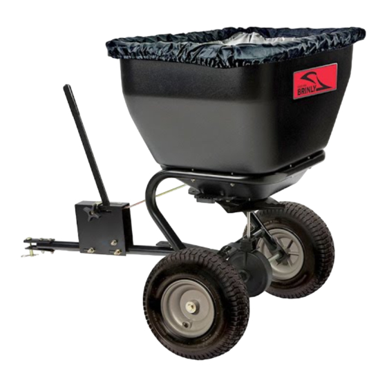
O W N E R ' S M A N U A L
B R O A D C A S T S P R E A D E R
MODEL:
B S - 3 6
B S - 2 6
•
Assembly
•
Installation
•
Operation
•
Repair Parts
For use with Riders
and Lawn/Garden Tractors.
For the latest product updates & setup tips:
Visit us on the web!
www.brinly.com
Important: This manual contains information for the safety of
persons and property. Read it carefully before assembly and
operation of the equipment!
L-1884-E
Advertisement
Table of Contents

Subscribe to Our Youtube Channel
Related Manuals for Brinly BS-36


Summary of Contents for Brinly BS-36
- Page 1 Lawn/Garden Tractors. For the latest product updates & setup tips: Visit us on the web! Important: This manual contains information for the safety of persons and property. Read it carefully before assembly and www.brinly.com operation of the equipment! L-1884-E...
-
Page 2: Table Of Contents
INTRODUCTION CONGRATULATIONS on your new Brinly-Hardy Broadcast Spreader! Your Spreader has been designed, engineered and manufactured to give you the best possible dependability and performance. Should you experience any problem you can not easily remedy, please do not hesitate to contact our knowledgeable customer service department toll-free at 1-877-728-8224. -
Page 3: Safety
SAFETY Read the general safety operating precautions in your towing vehicle • Keep all nuts, bolts and screws tight to be sure the equip- operator's manual for additional safety information. ment is in safe working condition. Operate Safely • The vehicle and attachment should be stopped and inspected for damage after striking a foreign object. -
Page 4: Parts Reference
PARTS REFERENCE EXPLODED VIEW FOR COMPOSITE (PLASTIC) WHEELS ASSEMBLY FOR METAL WHEELS ASSEMBLY FOR COMPOSITE (PLASTIC) WHEELS ASSEMBLY FOR METAL WHEELS ASSEMBLY Tools Required for Assembly: • 1/2” Wrench (2) • 7/16” Wrench (2) • Pliers • Flat Head Screwdrivers L-1884-E... -
Page 5: Parts List
B-4786 B-4786 Nylon Lock Nut 5/16” 877.728.8224 or email D-146P D-146P Hairpin Cotter 1/8” customerservice R-892-10 R-892-10 Clevis @brinly.com 50M0416P 50M0416P Pin, Cotter 1/8” x 1" F-436 F-436 Spring, Agitator, SS F-365 F-365 O-Ring, 3/8” I.D. AS-110 F-1015 F-1015 Transmission Assembly... -
Page 6: Parts List
BS-36BH Please call our Customer Service Department Toll-Free at 877.728.8224 F-574 F-574 Bearing, Shaft or email customerservice 2M0820SS 2M0820SS Bolt, Hex 1/4”x1-1/4” SS @brinly.com 45M0909SS 45M0909SS Washer, Plain SS F-577 F-577 E-Ring, 5/8” B-7392 B-7392 Plate, Directional Control B-7391 B-7391... -
Page 7: Assembly
ASSEMBLY INSTALL HOPPER SUPPORT Figure 1. TO THE HOPPER 1a. Install six 1/4 x 1-3/4 in. hex bolts (4), and 1/4 in. thrust washer (3) through top of hopper (2) and through support frame (1), as shown. 1b. Secure bottom of bolt with 1/4 in. lock- nut (5). - Page 8 ASSEMBLY Figure 3. ASSEMBLY FAN TO TRANSMISSION 3a. Slide the Fan Driver (24) and Fan (25) on to the shaft of the Transmission Assembly (21) until both reach the Pin Spring (23) Note: This is for pre-assembly only. Final adjustment of the fan is made later. Fan Driver Qty.
- Page 9 ASSEMBLY Figure 4. INSTALL TRANSMISSION & AXLE BACK 4a. Maneuver the transmission assembly (21) shaft into the center hole of the Hopper Assembly (2). Ensure that the slot of the transmission brace rests on top of the two tow tube hex nuts previously installed in Figure 2, as shown.
- Page 10 ASSEMBLY Figure 5-1. INSTALL WHEELS (METAL) Note: The unit will be shiped with one of two types of wheels. Determine whether the wheels have metal or composite (plastic) rims. If the rim is metal, proceed to step 5a. If the rim is plastic, proceed to step 5a.
- Page 11 ASSEMBLY ASSEMBLY Figure 5-2. INSTALL COMPOSITE WHEELS (PLASTIC) 5c.Attach each Wheel (9) to the Axle (6) using hardware in the following order: • One Axle Bearing (7) • One Flat Washer 5/8” (8) • One Spacer (42) • One or two Flat Washer 5/8” (8) - use 1 or two as needed.
- Page 12 ASSEMBLY Figure 6. FAN ADJUSTMENT 6a. Adjust fan upwards on shaft as close as possible to the bottom of the hopper with- out touching during operation. Note: The fan and fan driver normally rests on the spring pin, but may be adjusted upward approximately 1/8 of and inch.
- Page 13 ASSEMBLY Figure 7. INSTALL AGITATOR 7a. Place O-Ring (20) over transmission shaft. Slide down to hopper bottom to cre- ate seal. 7b. Slide Agitator Spring (20) over transmis- sion shaft. 7c. Insert Cotter Pin (18) through hole at top of transmission shaft. Flair ends to keep in place, as shown.
- Page 14 ASSEMBLY Figure 8. INSTALL CLEVIS 8a. Attach the upper and lower Clevis (17) halves to the Tow Tube (28). Secure with two 5/16”x2” Carriage Bolts (14) and two 5/16” Nylon Hex Nuts (15), as shown. 8b. Insert 1/2”X2-1/2” Hitch Pin in to Clevis and secure using Hairpin Cotter (16), as Hitch Pin 1/2”...
- Page 15 ASSEMBLY Figure 9. ASSEMBLE GAGE PLATE 9a. Insert Stop Handle (31) through slot opening at the top of the Gauge Plate (11). 9b. Insert the ‘S’ shaped end of Link Rod (12) through the upper hole of the Flow Control Handle (31). 9c.
- Page 16 ASSEMBLY Figure 10a. ATTACH GAGE PLATE TO SPREADER 10a. Rotate assembled Gage Plate (11) approximately 90° clockwise and insert formed end of the of the Link Rod (12) in to the hole provide on the Hopper (10) control plate, as shown. 10b.
- Page 17 ASSEMBLY Figure 10b. ATTACH GAGE PLATE TO SPREADER 10c. Attach the Gage Plate to the Tow Tube (28) as shown, using hard- ware provided: Do tighten the hex nuts until after calibrating the gage plate. • Two 5/16”x2-3/4” Hex Bolt (36) •...
-
Page 18: Calibration
CALIBRATION Figure 11. CALIBRATE GAGE PLATE 11a. Loosen the knob (29) and move to the #10,OPEN position, retighten. 11b. Move Flow Control Handle (31) to the #10, OPEN position. 11c. Ensure that hopper control gate (48) opens fully, if not slide the gage plate (11) forward or backward until control gate is fully open 11d.Tighten gage plate securely to theTow... -
Page 19: Operation
OPERATION Operation DIRECTIONAL CONTROL - ONE SIDE ONLY SPREADING The Fan speed and the spread width are controlled by the speed of the vehicle. The recommended operating speed is The directional control plate can be used for adjusting the slightly faster than that of a brisk walk, approximately 3 MPH material spread pattern when spreading near sidewalks, plant- (equal to the vehicle traveling 40 ft. -
Page 20: Annual Maintenance
ANNUAL MAINTENANCE Figure 12. Remove Wheels Clean Parts Lubricate bearings and axle lightly. Remove cotter from transmission housing Remove axle L-1884-E... - Page 21 ANNUAL MAINTENANCE Figure 13. Remove Gage Plate. L-1884-E...
- Page 22 ANNUAL MAINTENANCE Figure 14. Remove transmission bracket. Remove Transmission. Clean Fan L-1884-E...
-
Page 23: Annual Maintenance
ANNUAL MAINTENANCE Figure 15. 10. Remove the 4 bolts that hold the Gate and Directional Control Plate. Separate parts, as shown. 12. Clean parts thoroughly with soap and water. L-1884-E... -
Page 24: Media Flow Settings
MEDIA FLOW SETTINGS FLOW SETTINGS Some products may not be available in all areas. Flow control settings are based on 3 mph forward speed. The Table 1 is a list of flow control settings for specific products avail- able for use with the spreader. CAUTION: Avoid injury! Chemicals can be dangerous. - Page 25 MEDIA FLOW SETTINGS Table 1: Flow Control Settings for Specific Fertilizer's, Insecticides, Grass Seeds (Cont’d) lbs/1000 Flow Control Media sq. ft. Setting Lesco Pre-M.86% Plus Fertilizer 25-0-7 Lesco Starter Fertilizer 18-24-12 Lesco Turf Fertilizer 24-2-11 Lesco Weed and Feed Master Turf Ultimate Tall Fescue Blend Master Turf Ultimate Tall Fescue Blend Milogranite 6-2-0 Milogranite 6-2-0...
-
Page 26: Media Flow Settings
MEDIA FLOW SETTINGS Table 1: Flow Control Settings for Specific Fertilizer's, Insecticides, Grass Seeds (Cont’d) lbs/1000 Flow Control Media sq. ft. Setting Scotts Grubex Season Long Grub Control Scotts Grubex Season Long Grub Control Scotts Lawn Fungus Control Scotts Lawn Fungus Control Scotts Pure Premium Kentucky Bluegrass Mix Scotts Pure Premium Kentucky Bluegrass Mix Scotts Pure Premium Sun &... -
Page 27: Troubleshooting
TROUBLESHOOTING Table 2: Troubleshooting - Spreading Difficulties & Remedies PROBLEM CAUSE/CONDTION REMEDY Too much/not enough Gage Plate not calibrated Insure Gage Plate is properly calibrated, (Refer to Figure 11). material dispensed. Flow Control Handle Gate(47) and directional con- Remove and clean the Gate and Directional Control Plate with hard to operate or trol plate(46) clogged with soap and water, (Refer to Figure 12 through Figure 15). -
Page 28: Warranty
MANUFACTURER’S LIMITED WARRANTY Pull Behind Accessories The limited warranty set forth below is given by Brinly-Hardy The provisions as set forth in this warranty provide the sole and Company with respect to new merchandise purchased and exclusive remedy arising from the sale. Brinly-Hardy Co. shall used in the United States, its possessions and territories.
Need help?
Do you have a question about the BS-36 and is the answer not in the manual?
Questions and answers