Advertisement
Quick Links
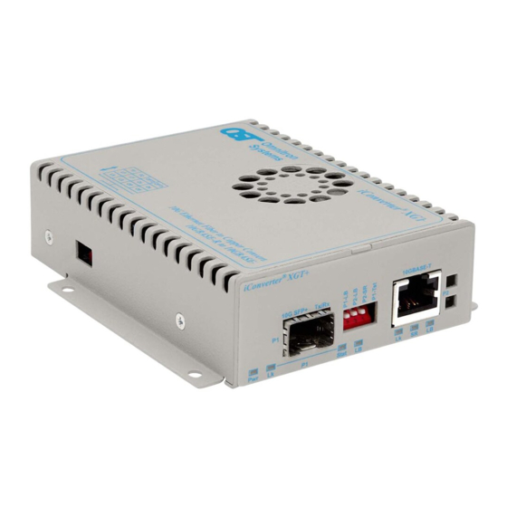
iConverter XGT+
Standalone Module User Manual
This User Manual describes the functions of the iConverter XGT+ Revision 2. The product
revision can be found on the label on the bottom of the module. The label is marked xx/yy,
where yy is the revision number.
Product Overview
The iConverter XGT+ is a 10 Gigabit Ethernet media converter with one 10GBASE-T RJ-45
port and one pluggable transceiver port that provides copper-to-fiber and copper-to-copper
media conversion. Copper-to-fiber conversion is achieved with XFP or SFP+ fiber transceivers.
Copper-to-copper conversion is achieved with a CX4 XFP transceiver.
The XGT+ supports high-power (power level 4) XFP transceivers, and the latest generation
of wavelength tunable DWDM XFP transceivers.
Installation Procedure
1) Configure DIP-switches
2) Install Standalone Module and Connect Cables
3) Verify Operation
1) CONFIGURE DIP-SWITCHES
DIP-SWITCH BANK 1
The location of the DIP-switches is shown in
Figure 1.
The function of DIP-switch Bank is outlined in
Figure 2.
DOWN
Switch
(Default)
SW1
Normal
SW2
Normal
SW3
Normal
SW4
Normal
Figure 2: DIP-switch BANK 1 Definitions
SW1 - P1 LOOPBACK "P1-LB"
When this DIP-switch is in the DOWN position (factory default), port P1 loopback is disabled.
When this DIP-switch is in the UP "P1-LB" position, loopback is enabled on port P1. When
enabled, all data received on port P1 is transmitted out port P1 and the connection between
port P1 and port P2 is interrupted.
NOTE: Simultaneous loopback of port P1 and port P2 is not supported on XFP models.
Page 1
UP
P1 Loopback Enabled
P2 Loopback Enabled
P2 Short Range
P1 Built-In Self Test (BIST)
SW2 - P2 LOOPBACK "P2-LB"
When this DIP-switch is in the DOWN position (factory default), port P2 loopback is disabled.
When this DIP-switch is in the UP "P2-LB" position, loopback is enabled on port P2. When
enabled, all data received on port P2 is transmitted out port P2 and the connection between
port P2 and port P1 is interrupted.
NOTE: Simultaneous loopback of port P1 and port P2 is not supported on XFP models.
SW3 - P2 Short Range
When this DIP-switch is in the DOWN position (factory default), port P2 short range feature
is disabled. When disabled, port P2 will support up to 100 meters of CAT 6A cabling. When
this DIP-switch is in the UP "P2-SR" position, port P2 will support up to 30 meters of CAT 5E
or better cabling in a reduced power consumption mode. The SR LED will be illuminated
indicating Short Range is enabled.
SW4 - P1 BIST (SFP+ Model Only)
When this DIP-switch is in the DOWN position (factory default), port P1 Built-In Self Test is
disabled. When this DIP-switch is in the UP "P1-Tst" position, the port will transmit a Pseudo
Random Bit Sequence (PRBS).
When two XGT+ converters are connected via port P1 (Port 1 to Port 1), the BIST function is
supported. The XGT+ initiating BIST (DIP-switch SW4 UP) will generate and send a PRBS
pattern out Port 1 to the other module. The receiving XGT+ will detect a good test pattern
and return a PRBS acknowledgement test pattern back to the initiating XGT+.
A successful test will produce a green blinking (5Hz) P1 LB LED on the initiating XGT+ and
a green blinking (1Hz) P1 LB LED on the receiving XGT+. If the initiating XGT+ does not
receive a valid response, the P1 LB LED will be blinking amber (5Hz). When BIST is initiated,
the traffic received on Port 2 of both converters will be discarded.
If loopback has been initiated, the BIST DIP-switch will be ignored. If BIST has been initiated,
the loopback DIP-switches will be ignored.
NOTE: The XGT+ modules must be the same revision for the BIST function to operate
correctly.
DIP-SWITCH BANK 2
LINK MODES
SW1 and SW2 - LINK MODES
These DIP-switches configure the different link modes available on the XGT+. It is
recommended to have link modes set to Link Segment (default setting - all DOWN) during
the initial installation. After the circuit has been tested and operational, configure the module
for the desired mode. Refer to Figure 3 for configuration options.
SW1
SW2
Function
DOWN
DOWN
Link Segment (default)
UP
DOWN
Asymmetrical Link Propagate P1 to P2
DOWN
UP
Asymmetrical Link Propagate P2 to P1
UP
UP
Symmetrical Link Propagate
Figure 3: DIP-switch BANK 2 Link Modes
For detailed information on the operation of the different Link Modes, download the application
note "iConverter Link Modes" available on Omnitron's web page:
http://www.omnitron-systems.com/downloads_iconverter.php
Page 2
Advertisement

Related Manuals for Omnitron Systems Technology iConverter XGT+


Summary of Contents for Omnitron Systems Technology iConverter XGT+
- Page 1 SW2 - P2 LOOPBACK “P2-LB” When this DIP-switch is in the DOWN position (factory default), port P2 loopback is disabled. When this DIP-switch is in the UP “P2-LB” position, loopback is enabled on port P2. When enabled, all data received on port P2 is transmitted out port P2 and the connection between iConverter XGT+ port P2 and port P1 is interrupted.
- Page 2 Figure 4: LED Indicators ©2016 Omnitron Systems Technology, Inc. iConverter is a registered trademark of Omnitron Systems Technology, Inc. Trademarks are owned by their respective companies. Specifications subject to change without notice. All rights reserved. 040-8589N-001B 4/16...
Need help?
Do you have a question about the iConverter XGT+ and is the answer not in the manual?
Questions and answers