Omnitron Systems Technology iconverter GX AN User Manual
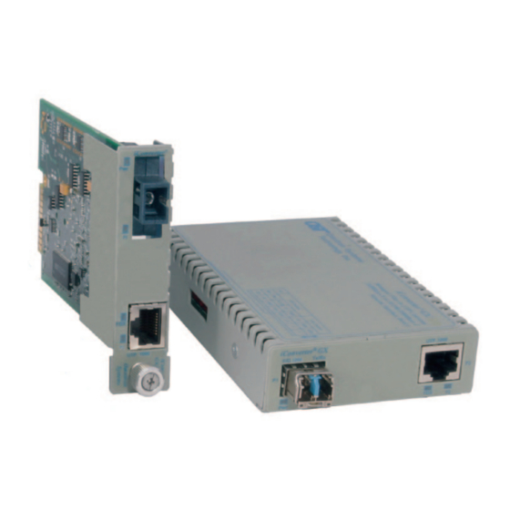
Standalone and plug-in module
Hide thumbs
Also See for iconverter GX AN:
- Quick start manual (2 pages) ,
- Quick start manual (2 pages)
Table of Contents
Advertisement
Quick Links
Advertisement
Table of Contents

Related Manuals for Omnitron Systems Technology iconverter GX AN


Summary of Contents for Omnitron Systems Technology iconverter GX AN
- Page 1 iConverter Gx AN Media Converter ® STANDALONE AND PLUG-IN MODULE USER MANUAL...
-
Page 2: Table Of Contents
Table of Contents Overview ...........................3 1.1 General Description ....................3 Port Structure........................3 2.1 Overview ........................3 2.1.1 RJ-45 and Fiber Ports ..................3 Installation Procedure .......................4 3.1 Overview ........................4 3.2 Configuring DIP-switches ..................4 3.2.1 DIP-switch Settings ..................4 3.3 Installing the Module and Connecting Cables ............6 3.3.1 Plug-In Modules ....................6 3.3.2 Standalone Modules ..................7 3.4 Verifying Operation ....................8 4.0 Configuring the Module via Command Line Interface............8... -
Page 3: Overview
OVERVIEW This document describes the installation and configuration of the iConverter Gx AN standalone and plug-in modules. GENERAL DESCRIPTION The Omnitron iConverter Gx AN provides 1000BASE-T copper to 1000BASE-X fiber media conversion. ® The fiber optic port supports auto and forced negotiation configuration via DIP-switches. The RJ-45 port automatically detects and advertises the Duplex and Pause abilities of connected copper devices. -
Page 4: Installation Procedure
INSTALLATION PROCEDURE OVERVIEW The following steps outline the installation and configuration procedures for the Gx AN. Refer to the specified sections for detailed instructions. • Configuring DIP-switches (Section 3.2) • Installing the Module and Connecting Cables (Section 3.3) • Verifying Operation (Section 3.4) When the setup and configuration procedures are completed, the Gx AN has been configured with the basic setup requirement for standard operation. - Page 5 When this DIP-switch is in the Manual “MAN” position, the advertised auto-negotiation capabilities of Port 2 is controlled by DIP-switches SW2 through SW5. Left / Down Switch Right / Up (Factory Default) P1 AN: P1 MAN: Port 1 Fiber Auto-negotiation Port 1 Fiber Manual negotiation SW2 -SW3 Port 2 (P2) advertised auto-negotiation capability - See Figure C SW4 - SW5 Pause Advertisement Mode - See Figure D SW6 - SW8...
-
Page 6: Installing The Module And Connecting Cables
Results Left / Down Left / Down Left / Down Left / Down Enables Link Segment mode (LS AN) (AN) Left / Down Right / Up Left / Down Left / Down Enables Link Propagate mode (LP AN) (AN) Right / Up Left / Down Left / Down Left / Down Enables Link Segment mode (LS MAN) (MAN) Right / Up Right / Up Left / Down Left / Down Enables Link Propagate mode (LP MAN) (MAN) Right / Up Enables Remote Fault Detection mode + Link Left / Down Right / Up Left / Down (MAN) Segment (RFD+LS) Right / Up Enables Remote Fault Detection mode + Link Right / Up Right / Up Left / Down (MAN) Propagate (RFD+LP) Right / Up Left / Down Left / Down Right / Up... -
Page 7: Standalone Modules
3.3.2 Standalone Modules The Gx AN standalone media converter is available in tabletop and wall-mounting models. For wall- mounting, attach the Gx AN to a wall, backboard or other flat surfaces. For tabletop installation, place the unit on a flat and level surface. Attach the rubber feet to the bottom of the Gx AN to prevent the unit from sliding. -
Page 8: Verifying Operation
VERIFYING OPERATION Once the module has been installed and configured, per Sections 3.2 - 3.3, verify the module is operational by viewing the status of the LED indicators. The table below provides a description for each LED indicator. The Power LED indicates the module is receiving power from the chassis. The Fiber Optic “FO”... - Page 9 Password Entry screen will be skipped and will go straight to the Management Options screen. If a password has been set, the Password Entry screen will be displayed. Type the password and press <ENTER>, the Management Module will respond with the Management Options screen. Omnitron Systems Technology, Inc. iConverter Copyright 2001-2016 OST, Inc.
- Page 10 NOTE: Module configuration is also available using NetOutlook. Chassis Selection iConverter Number Chassis Name NMM2 Not Available Not Available Not Available Not Available Not Available Not Available Not Available Not Available Not Available Not Available Not Available Not Available Not Available Not Available Not Available Not Available...
- Page 11 Module - iConverter Gx AN iConverter Identifier - Chassis Number Slot Number Model Number = 8519N-1 Serial Number = 00005312 Manufacturing Date = 20071024 Product Revision Software Revision = 1.6 Switch ON Condition OFF Condition H/W Actual 1: Power = On...
-
Page 12: Sfp Status
4.2.1 SFP Status The Gx AN module installed with an SFP will provide general and specific information on the SFP. This information is best viewed with SNMP management software. The following is the information available: 4.2.1.1 SFP A0 Information Display This section displays fixed SFP Module information for the following areas. - Page 13 SFP Information - iConverter Gx AN iConverter Identifier - Chassis Number = 1 Slot Number = 5 Model Number = 8519N-1 Port = 1 Address A0 Page Contents =================================================== 00: 03 04 07 00 00 00 02 12 00 01 01 01 0D 00 0C 78 ....x 10: 00 00 00 00 4F 6D 6E 69 74 72 6F 6E 20 53 79 73 ..Omnitron Sys...
-
Page 14: Gx An Specifications
GX AN SPECIFICATIONS iConverter Gx AN Description 1000BASE-T Copper to 1000BASE-X Fiber Media Converter Standard IEEE 802.3 Compliances Regulatory UL, CE, FCC Class A, RoHS2 (6/6), WEEE, REACH Compliances Frame Size Supports frame sizes up to 10K bytes Copper: 1000BASE-T (RJ-45) Fiber: 1000BASE-SX (ST, SC, LC, SFP) Port Types 1000BASE-LX (ST, SC, LC, SFP) 1000BASE-ZX (SC, SFP) 1000BASE-BX (SC, SFP) Copper: EIA/TIA 568A/B, Cat 5 UTP and higher Cable Types Fiber: Multimode: 50/125µm, 62.5/125µm Single-mode: 9/125µm AC Adapter: 100 - 120VAC/60Hz (US) 0.04A @ 120VAC (max) AC Power Requirements AC Adapter: 100 - 240VAC/50 - 60Hz... -
Page 15: Troubleshooting Guide
Possible Causes:. A. Confirm that the UTP cable is connected properly to the iConverter Gx AN and the attached copper device. B. Verify the Link Mode selection is set to Link Segment (LS). Until a stable link is established, leave the Link Mode configured for LS. -
Page 16: Issues
The RJ-45 link LED does not illuminate after installation is complete. Possible Causes: A. Confirm that the UTP cable is connected properly to the iConverter Gx AN and the attached copper device. Once a connection has been established between the iConverter and its link partner (switch or workstation), the corresponding Port 2 (P2) LED should illuminate. -
Page 17: Warranty
Orange in California and each party consents to the jurisdiction of those courts. The information contained in this publication is subject to change without notice. Omnitron Systems Technology, Inc. is not responsible for any inadvertent errors. -
Page 18: Customer Service Information
CUSTOMER SERVICE INFORMATION If you encounter problems while installing this product, contact Omnitron Technical Support: Phone: (949) 250-6510 Fax: (949) 250-6514 Address: Omnitron Systems Technology, Inc. 38 Tesla Irvine, CA 92618, USA Email: support@omnitron-systems.com URL: www.omnitron-systems.com 041-8500N-001B 4/17 Page 18...
Need help?
Do you have a question about the iconverter GX AN and is the answer not in the manual?
Questions and answers