Table of Contents
Advertisement
Quick Links
Trademarks
FOXWELL is trademark of Shenzhen Foxwell Technology Co., Ltd.
All other marks are trademarks or registered trademarks of their respective
holders.
Copyright Information
©2020 Shenzhen Foxwell Technology Co., Ltd.
All rights reserved.
Disclaimer
The information, specifications and illustrations in this manual are based on the
latest information available at the time of printing.
Foxwell reserves the right to make changes at any time without notice.
Visit our website at
www.foxwelltech.us
For Technical Assistance, send us email at
support@foxwelltech.com
1
Premier Diagnostic Platform I75TS User's Manual V1.01
Advertisement
Table of Contents

Related Manuals for Foxwell I75TS


Summary of Contents for Foxwell I75TS
- Page 1 Disclaimer The information, specifications and illustrations in this manual are based on the latest information available at the time of printing. Foxwell reserves the right to make changes at any time without notice. Visit our website at www.foxwelltech.us For Technical Assistance, send us email at support@foxwelltech.com...
-
Page 2: One-Year Limited Warranty
FOXWELL. 3 The customer shall bear the cost of shipping the product to FOXWELL. And FOXWELL shall bear the cost of shipping the product back to the customer after the completion of service under this limited warranty. - Page 3 The customer will be billed for any parts or labor charges not covered by this limited warranty. d) FOXWELL will repair the Product under the limited warranty within 30 days after receipt of the product. If FOXWELL cannot perform repairs covered...
- Page 4 (the Consumer). This limited warranty gives the Consumer specific legal rights and the Consumer may also have other rights which vary from state to state. Premier Diagnostic Platform I75TS User's Manual V1.01...
-
Page 5: Safety Information
● Do not exceed voltage limits between inputs specified in this user’s manual. ● Always wear ANSI approved goggles to protect your eyes from propelled objects as well as hot or caustic liquids. Premier Diagnostic Platform I75TS User's Manual V1.01... - Page 6 ● Block drive wheels before testing with engine running. Put the transmission in park (for automatic transmission) or neutral (for manual transmission). And never leave a running engine unattended. ● Do not wear jewelry or loose fitting clothing when working on engine. Premier Diagnostic Platform I75TS User's Manual V1.01...
-
Page 7: Table Of Contents
4.1 VIN R ..........................25 EADING 4.1.1 Automatic Read........................ 25 4.1.2 Scan VIN .......................... 26 4.1.2.1 Scan VIN Plate ......................26 4.1.2.2 Scan Barcode/QR Code of VIN ................27 4.1.2.3 Photo Recognition ....................29 Premier Diagnostic Platform I75TS User's Manual V1.01... - Page 8 6.12 K ..................... 59 ROGRAMMING MMOBILIZER 7 TPMS SERVICE OPERATIONS ....................59 7.1 N ..........................59 AVIGATION 7.2 T ....................... 61 RIGGER PERATIONS 7.3 R ......................70 ELEARN PERATIONS 8 DATA MANAGER ......................... 72 Premier Diagnostic Platform I75TS User's Manual V1.01...
- Page 9 12.2 W ......................96 ORKSHOP NFORMATION 12.3 C ......................96 USTOMER NFORMATION 13 MY ACCOUNT ..........................97 13.1 M .......................... 97 CCOUNT 13.2 M ........................98 RODUCTS 13.3 F ....................98 EEDBACK AND SUGGESTIONS Premier Diagnostic Platform I75TS User's Manual V1.01...
-
Page 10: Using This Manual
Bold text is used to highlight selectable items such as buttons and menu options. Example: Select Diagnostic from home screen of the I75TS application. 1.2 Symbols and Icons 1.2.1 Solid Spot Operation tips and lists that apply to specific tool are introduced by a solid spot ●. -
Page 11: Note And Important Message
Do not soak scanner as water might find its way into the scanner. 2 Introduction The latest Android tablet scanner I75TS delivers faster and smarter diagnosis for workshops and technicians. Through hardware and software upgrades, technical staff can now approach problems with greater speed and accuracy and produce comprehensive, professional reports. - Page 12 2 Power Indicator - indicates the power status of the scanner. 3 Charging Indicator - indicates the charging status of the scanner. Figure 2-2 Back View 4 Rear-Facing Camera - takes pictures of VIN number, faulty parts and plates and shoots test videos. Premier Diagnostic Platform I75TS User's Manual V1.01...
-
Page 13: Vci Dongle Descriptions
Do not use solvents such as alcohol to clean display. Use a mild nonabrasive detergent and a soft cotton cloth. 2.2 VCI Dongle Descriptions I75TS connects to the vehicle and get data through the VCI dongle either by Bluetooth or USB communication. Premier Diagnostic Platform I75TS User's Manual V1.01... - Page 14 1 Error Light - illuminates constantly when serious hardware failure occurs. 2 USB Light - turns green when the VCI dongle is properly connected and communicating with the I75TS tablet via USB cable. 3 Bluetooth Light - turns green when the VCI dongle is properly connected with the I75TS tablet via Bluetooth communication.
- Page 15 Figure 2-7 Bottom View of VCI 6 USB Port - provides USB connection between the VCI dongle and I75TS tablet. Premier Diagnostic Platform I75TS User's Manual V1.01...
-
Page 16: Accessories
USB 2.0 OTG/standard USB 2.0 HOST interface Bluetooth 5.0 (10-20 m) Camera 5 megapixels rear-facing 8000mAh, Lithium-polymer battery, chargeable via 12V/3A USB power Built-in Battery supply Protocols ISO9141-2, ISO14230-2, ISO15765-4, K/L lines, Double K Line Premier Diagnostic Platform I75TS User's Manual V1.01... -
Page 17: Getting Started
Internal Battery Pack ● External Power Supply 3.1.1 Internal Battery Pack The I75TS tablet can be powered with the internal rechargeable battery. The fully charged battery is capable of providing power for 14 hours of continuous operation. NOTE Please turn off the tablet to save power when not use. -
Page 18: Establishing Vehicle Communication
Figure 3-1 Power-off Prompt Screen To shut down the scanner: 1. Press and hold the Power button of the I75TS for 5 seconds. 2. Click the Power off to shut down or Reboot to restart. 3.3 Establishing Vehicle Communication To establish communication with I75TS: 1. -
Page 19: Vci Connection
3. Check the VCI Indicator status at the toolbar. If the button turns to green, the I75TS is ready to start vehicle diagnosis. 3.3.1 VCI Connection The VCI dongle supports two ways of communication with the I75TS tablet: ● Bluetooth Communication ● USB Communication 3.3.1.1 Bluetooth Communication... - Page 20 Figure 3-6 Sample VCI Indicator Status Screen NOTE If the VCI Indicator isn’t green, it indicates that the signal strength of the transmitter is too weak to be detected. In this case, try to get closer to the Premier Diagnostic Platform I75TS User's Manual V1.01...
-
Page 21: Usb Communication
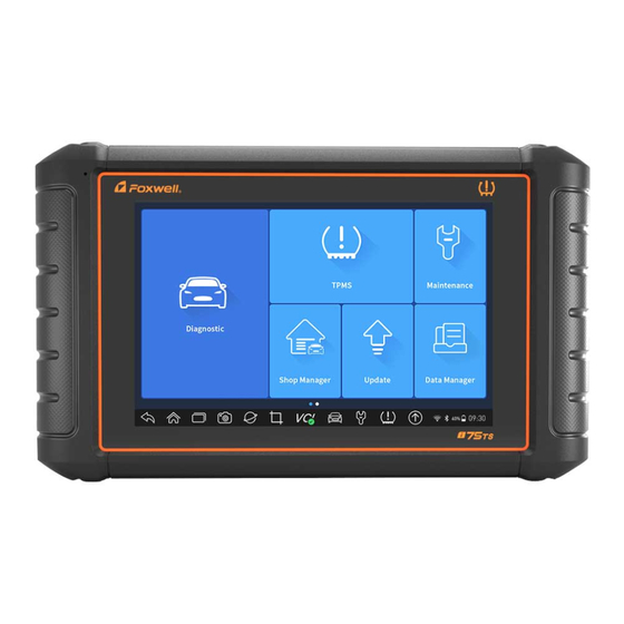
USB Type B cable, and the VCI Indicator will turn green, indicating the dongle has connected to the tablet. 3.4 Screen Layout of Home Screen When the tablet boots up, press the I75TS desktop icon to launch the diagnostic application. Figure 3-7 Sample Home Screen 1. -
Page 22: Navigation Toolbar
Data Manager - leads to screens for saved screenshots, pictures and test reports, and playing back live data, as well as debug logging data. ● Update - leads to screens for Foxwell ID registration and updating the scanner. ● VCI Manager - leads to screens for making Bluetooth pairing of VCI dongle and tablet, updating the VCI firmware and binding/unbinding VCI dongle. -
Page 23: Diagnostic Menu
Table 3-1 Tool Bar 3.4.3 Diagnostic Menu Touch Diagnostic at the I75TS application menu, and the Diagnostic menu will display. The operations of the buttons on Diagnostic menu are described in the below table. Premier Diagnostic Platform I75TS User's Manual V1.01... -
Page 24: Vehicle Identification
Each selection you make advances you to the next screen. Exact procedures may vary somewhat by vehicle. It typically identifies a vehicle by any of the following means: ● VIN Reading ● Manual Selection Premier Diagnostic Platform I75TS User's Manual V1.01... -
Page 25: Vin Reading
Automatic Read allows to identify a vehicle by automatically reading the vehicle identification number (VIN). To identify a vehicle by Automatic Read: 1. Select Diagnostic from home screen of the I75TS application. 2. Click VIN and choose Automatic Read from the option list. Figure 4-2 Sample Automatic Read Screen... -
Page 26: Scan Vin
4.1.2.1 Scan VIN Plate To identify a vehicle by Scan VIN Plate: 1. Select Diagnostic from home screen of the I75TS application. 2. Click VIN button and choose Scan VIN from the option list. 3. Find the VIN plate of your car, and put the VIN number into the scanning box. -
Page 27: Scan Barcode/Qr Code Of Vin
4. If failed, please click Close to quit and input the VIN manually. 4.1.2.2 Scan Barcode/QR Code of VIN To identify a vehicle by Scan QR Code: 1. Select Diagnostic from home screen of the I75TS application. Premier Diagnostic Platform I75TS User's Manual V1.01... - Page 28 Vehicle Specification or VIN code is correct, press the Confirm to continue. If incorrect, you are allowed to modify VIN number manually. The scan box can be zoomed in or zoomed out. Figure 4-9 Sample Scan QR Code Screen Premier Diagnostic Platform I75TS User's Manual V1.01...
-
Page 29: Photo Recognition
4.1.2.3 Photo Recognition To identify a vehicle by Photo Recognition: 1. Select Diagnostic from home screen of the I75TS application. 2. Click VIN button and choose Scan VIN from the option list. 3. Find the VIN plate, QR code or barcode of your car, and put the content number into the scanning box. -
Page 30: Manual Entry
Manual Entry allows to identify a vehicle by inputting VIN manually. To identify a vehicle by Manual Entry: 1. Select Diagnostic from home screen of the I75TS application. 2. Click VIN and choose Manual Entry from the option list. 3. Press Keyboard button to input a valid VIN code and press OK to continue. -
Page 31: Manual Selection
Select vehicle brand you are to test, and two ways of getting to the diagnostic operations are available. ● Smart VIN ● Manual Selection Figure 4-15 Sample Vehicle Entry Screen Name Button Description Home Back to the Application Menu. Settings A shortcut for Settings menu. Premier Diagnostic Platform I75TS User's Manual V1.01... -
Page 32: Smart Vin
(VIN). To identify a vehicle by Smart VIN: 1. Select Diagnostic from home screen of the I75TS application. 2. A screen with vehicle manufacturers displays. Select the area where the vehicle manufacturer from. A menu of all vehicle manufacturers displays. -
Page 33: Manual Vehicle Selection
VIN characters, such as model year, and engine type. To identify a vehicle by manual vehicle selection: 1. Select Diagnostic from home screen of the I75TS application. 2. A screen with vehicle manufacturers displays. Select the area where the vehicle manufacturer is from. -
Page 34: Vehicle History
To identify a vehicle by Vehicle History: 1. Select Diagnostic from home screen of the I75TS application. 2. Select History button at the top of the diagnostic page and the diagnostic records will display. -
Page 35: Diagnosis
When you completed the identification of vehicle, you have to identify the control modules installed in the vehicle. There are two ways to identify the controllers installed in a car: ● Quick Scan ● Control Modules Premier Diagnostic Platform I75TS User's Manual V1.01... -
Page 36: Quick Scan
Figure 5-3 Sample Quick Scan Screen 3. At the end of successful automatic controller scan, a menu with a list of DTC displays and click button to the right to view DTC descriptions. Premier Diagnostic Platform I75TS User's Manual V1.01... - Page 37 4. Press Report to create an overview of installed control units and their system status, or press Save to save the report. Press Erase to clear the information. Figure 5-5 Sample DTC Save Screen Figure 5-6 Sample Report Screen Premier Diagnostic Platform I75TS User's Manual V1.01...
-
Page 38: Control Modules
It is useful for technicians who are familiar with the vehicle specifications. To select a system to test: 1. Press Control Modules from the menu and a controller menu displays. Premier Diagnostic Platform I75TS User's Manual V1.01... -
Page 39: Diagnostic Operations
Active Test ● ECU Information ● Special Functions NOTE Not all function options listed above are applicable to all vehicles. Available options may vary by the year, model, and make of the test vehicle. Premier Diagnostic Platform I75TS User's Manual V1.01... -
Page 40: Read Codes
Figure 5-11 Sample Trouble Code Screen ● Freeze Frame- select one fault code from the code list and click Freeze Frame button on the screen. The screen will display freeze frame data, a Premier Diagnostic Platform I75TS User's Manual V1.01... - Page 41 Figure 5-13 Sample Freeze Frame Screen ● Help - select one fault code from the code list and click Help button on the screen. The screen will display the detailed descriptions about the fault code and repair guide. Premier Diagnostic Platform I75TS User's Manual V1.01...
-
Page 42: Clear Codes
Clear Codes does not fix the problem that caused the fault! DTCs should only be erased after correcting the condition(s) that caused them. To clear codes: 1. Press Clear Codes from Select Diagnostic Function menu. Figure 5-15 Sample Function Menu Screen Premier Diagnostic Platform I75TS User's Manual V1.01... -
Page 43: Live Data
1. Press Live Data from Select Diagnostic Function menu to display the live data menu. Figure 5-16 Sample Function Menu Screen 2. Press All Data from the menu to display the data stream screen. All readings will be displayed in text format by default. Premier Diagnostic Platform I75TS User's Manual V1.01... - Page 44 Click the dropdown list at the upper left of the screen to enter to choose a working condition to learn. Premier Diagnostic Platform I75TS User's Manual V1.01...
- Page 45 To view another PID plot, tab the name of a plot and a list of available PIDs display. Select one from the dropdown box and the plot changes to the newly selected PID. Premier Diagnostic Platform I75TS User's Manual V1.01...
- Page 46 ● Merge Graph: merges multiple PID plots into one coordinate, so you can easily see how they affect each other, providing you with the most comprehensive and functional look at live data possible. Premier Diagnostic Platform I75TS User's Manual V1.01...
-
Page 47: Custom List
Figure 5-24 Sample Live Data Screen 5.2.4 ECU Information ECU Information screen displays the identification data of the control module under test, such as the control module identification string and the control module coding. Premier Diagnostic Platform I75TS User's Manual V1.01... -
Page 48: Active Tests
The sequence, number and type of tests are dictated by the control module. On some systems, the actuator tests cannot be restarted until the ignition key is switched off for some time. Alternatively, briefly start and run the engine, Premier Diagnostic Platform I75TS User's Manual V1.01... - Page 49 2. Select an option to start the test and live data of the selected test displays. Figure 5-28 Sample Active Test Screen 3. Follow on-screen instructions to make proper selections and operations to complete the tests. 4. Press to exit. Premier Diagnostic Platform I75TS User's Manual V1.01...
-
Page 50: Special Functions
The Service section is specially designed to provide you quick access to the vehicle systems various scheduled service maintenance performances. To start a service function: 1. Select Special Functions from main menu and press ENTER to confirm. Figure 5-29 Sample Main Menu Screen Premier Diagnostic Platform I75TS User's Manual V1.01... -
Page 51: Coding And Programming
Figure 5-31 Sample Service Function Screen 5.3.2 Coding and Programming I75TS allows for the coding and programming of a replacement control module or changing previously stored incorrect coding. Coding also is known as Teach-in Program or Component Adaptation. It is the process of selecting and activating one program for a specific vehicle from a set of programs that the factory installed in the control module. - Page 52 2. Select Programming option from the Special Functions menu. A list of available services display. Figure 5-33 Sample Special Functions Screen 3. Select the function you want to test. Follow on-screen instructions to make proper selections and operations to complete the tests Premier Diagnostic Platform I75TS User's Manual V1.01...
-
Page 53: Hot Functions
2. Select Hot Functions option from the Special Functions menu. A list of available services display. Figure 5-36 Sample Special Functions Screen 3. Select the function you want to test. Follow on-screen instructions to make proper selections and operations to complete the tests Premier Diagnostic Platform I75TS User's Manual V1.01... -
Page 54: Maintenance
The Service Indicator System is designed to alert the driver when the vehicle is due for a service. Oil service reset methods are determined by the vehicle being tested. Depending on the vehicle being tested, any of the following means displays: Premier Diagnostic Platform I75TS User's Manual V1.01... -
Page 55: Electronic Parking Brake (Epb) Service
Mercedes SBC vehicles - allows to change brake fluid/bleed brake system. ● Perform service reset and service position on BMW EPB vehicles - allows to do the CBS reset and CBS correction for front brake and rear brake. Premier Diagnostic Platform I75TS User's Manual V1.01... -
Page 56: Battery Replacement (Brt)
1. Replace the old battery with the new one. Ensure the key is not in the ignition. 2. Connect the scanner to the vehicle’s 16 pin Data Link Connector (DLC) with the diagnostic cable. Premier Diagnostic Platform I75TS User's Manual V1.01... -
Page 57: Diesel Particulate Filter (Dpf) Regeneration
SAS Calibration menu let you perform calibration of the Steering Angle Sensor, which permanently stores the current steering wheel position as straight-ahead in the sensor EEPROM. On successful calibration of the sensor, its fault memory is automatically cleared. Premier Diagnostic Platform I75TS User's Manual V1.01... -
Page 58: Continuous Variable Transmission (Cvt)
Air is compressible, so when the brakes are applied any air bubbles in the system must first be compressed before the hydraulic fluid will transmit pressure to apply the brakes. Premier Diagnostic Platform I75TS User's Manual V1.01... -
Page 59: Key Programming/Immobilizer
7 TPMS Service Operations The TPMS application is used to check the TPMS sensor conditions, program the Foxwell sensor T10, perform the TPMS Relearn procedure and basic TPMS diagnostic functions. 7.1 Navigation Tap the TPMS button from the home menu, the Vehicle Menu will appear. - Page 60 Figure 7- 3 Sample History Test Screen 7.1.1 TPMS Service Screen Layout The TPMS service typically include four functions: Trigger/Diagnosis/Programming/Study Help Figure 7- 4 Sample TPMS Service Screen Layout Premier Diagnostic Platform I75TS User's Manual V1.01...
-
Page 61: Trigger Operations
(front right), RR (rear right), RL (rear left) and SP (spare, if any). 4. Wheel with a feedback icon, red or green vertical rectangle, indicates sensor trigger has been finished. Refer to Table 7- 6 for details. Premier Diagnostic Platform I75TS User's Manual V1.01... - Page 62 The programming function is used to program the sensor data to the Foxwell sensor T10 and replace the faulty senor (poor battery life or malfunction). The i75TS is easy to use with a proven efficiency and guaranteed accurate results. There are four options available when programming Foxwell sensor T10 using the Display Tablet: Manual Create, Clone by Activation, Automatic Create (1-16),Clone by OBD.
- Page 63 ID, or Cancel to exit. NOTE: Sensors from different manufacturers may have different ID character length limits. The i75TS support input 8-bit characters or 10-bit characters which has range limitation, here we take 8bit input as example. Premier Diagnostic Platform I75TS User's Manual V1.01...
- Page 64 Figure 7- 8 Sample 8-bit Input Screen 5. Place the proper Foxwell sensor T10 near the top right of the Display Tablet to start programming. Premier Diagnostic Platform I75TS User's Manual V1.01...
- Page 65 7.2.2 Clone by Activation This function allows user to bypass OBD II and automatically write in the retrieved original sensor data to the Foxwell sensor T10. It is used after the original sensor is triggered. Premier Diagnostic Platform I75TS User's Manual V1.01...
- Page 66 ID will display. Figure 7- 11 Sample Clone by Activation Function Screen Then put the Foxwell T10 sensor that need to be programmed close to the device 0-20cm and sensors that not need to be programmed beyond 100cm.
- Page 67 3. Tap the Automatic Create functional button on the screen. Figure 7- 13 Sample Automatic Create Function Screen 4. Place the proper Foxwell sensor T10 near the top right of the Display Tablet to write the new created sensor ID into the Foxwell sensor T10.
- Page 68 Column 2 of the table. 7.2.4 Copy by OBD This function allows users to write the saved sensor information into Foxwell sensor T10 after performing Copy by OBD function, the sensor ID will appear Premier Diagnostic Platform I75TS User's Manual V1.01...
- Page 69 Copy by OBD button. Figure 7- 15 Sample Copy by OBD Function Screen Place the proper Foxwell sensor T10 near the top right of the Display Tablet, and tap OK to start programming the saved sensor information to the Foxwell T10.
-
Page 70: Relearn Operations
Figure 7- 17 Sample Relearn Function Main Screen To perform TPMS Relearn function 1. Establish the communication with the test vehicle via the Foxwell VCI box. Power on the Display Tablet. 2. Turn the ignition on but do not start the engine. - Page 71 1. Tap Read DTC button from the Relearn screen. 2. A data list of TPMS DTCs retrieved from the vehicle’s ECU will show up. 7.4.4 Clear DTC To clear DTCs 1. Tap Clear DTC from the Relearn screen. Premier Diagnostic Platform I75TS User's Manual V1.01...
-
Page 72: Data Manager
8.1 Image Image option leads to screens for review of stored screenshots. In case a failure of I75TS application or the Android system occurs, please just take a screenshot and send it to our team to help with the troubleshooting. -
Page 73: Review Image
Figure 8-3 Sample Screenshot Screen 8.1.2 Review Image To review the screenshots: 1. Press Data Manager from home screen of I75TS diagnostic application. 2. Press Image and all available pictures will be displayed. Premier Diagnostic Platform I75TS User's Manual V1.01... - Page 74 Print to print the pictures and press Rename to change the picture name. Figure 8-5 Sample Edit Picture Screen 4. Long press the screen to edit all pictures like Rename or Delete. Figure 8-6 Sample All Pictures Edit Screen Premier Diagnostic Platform I75TS User's Manual V1.01...
-
Page 75: Pdf Report
2. Add a description to the DPF report, and press the OK to save. 8.2.2 Review PDF Report To review the PDF reports: 1. Press Data Manager from home screen of I75TS diagnostic application. 2. Press PDF and all available PDF files will be displayed. Figure 8-8 Sample Browse PDF Screen 3. -
Page 76: Data Playback
(forward or reverse) can also be controlled. To review recorded live data: 1. Press Data Manager from home screen of I75TS diagnostic application. 2. Press Data Playback and all available records display. 3. Select one record and press Select All button or choose some parameters, then press the OK button to review. -
Page 77: Data Logging & Data Record
To create a debug data log: 1. When connected to a car, click the Data Logging icon to start record the communication data between the tablet and the vehicle. Premier Diagnostic Platform I75TS User's Manual V1.01... -
Page 78: Report
Figure 8-14 Sample Report Review Screen 9 VCI Manager VCI Manager allows you to make Bluetooth pairing between the tablet and the VCI dongle, update VCI firmware and unbind a VCI dongle. Premier Diagnostic Platform I75TS User's Manual V1.01... -
Page 79: Bluetooth
Update option allows you to update VCI firmware when the new version is available. To update the VCI dongle firmware: 1. Connect the VCI dongle to the I75TS tablet via USB or Bluetooth. And make sure the power supply will not be disturbed during the process of update. -
Page 80: Unbind Avci Dongle
9.3 Unbind a VCI dongle This option allows you to unbind a VCI dongle when the VCI dongle is defective or stolen. To unbind a VCI dongle: 1. Click the VCI Manager application on the I75TS Menu. Premier Diagnostic Platform I75TS User's Manual V1.01... - Page 81 2. Select Unbind a VCI dongle option from the option list and press OK to confirm. Figure 9-5 Sample Unbind Prompt Screen To bind a new VCI dongle: 1. Connect the VCI dongle with I75TS tablet via USB cable. Premier Diagnostic Platform I75TS User's Manual V1.01...
-
Page 82: Registration And Update
The scanner can be updated to keep you stay current with the latest development of diagnosis. This section illustrates how to register and update your scan tool. You can register both on Foxwell website or by the built-in update client. - Page 83 Code button. We will send a 4-digit verification code to the email you just entered. Find the security code in your mailbox, input the code, create a password and click Free Registration to complete. Premier Diagnostic Platform I75TS User's Manual V1.01...
- Page 84 Figure 10-4 Sample Registration Done Screen 5. The serial number will be recognized automatically and click Submit to activate the scanner. Figure 10-5 Sample Product Activation Screen 6. The product is registered successfully. Premier Diagnostic Platform I75TS User's Manual V1.01...
-
Page 85: Register Through Website
Figure 10-6 Sample Activation Done Screen 10.1.2 Register through Website To register through our website: 1. Visit Foxwell official website www.foxwelltech.us and press Register icon, or go to the registration page by selecting Support from home page and then click Register. - Page 86 Free Registration to complete. Figure 10-9 Sample Create Account Screen 3. Sign in to the Member Center, click New Registration, input the right serial number and click Submit to activate the product. Premier Diagnostic Platform I75TS User's Manual V1.01...
-
Page 87: Update
3. When all the items are updated, an “Update Done” message displays. NOTE Please make sure your network works correctly and the tablet is fully charged or connect to external power supply. Figure 10-11 Sample Update Screen Premier Diagnostic Platform I75TS User's Manual V1.01... -
Page 88: Settings
Select Language opens a screen that allows you to choose system language. To configure system language: 1. Press Settings from home screen of the I75TS diagnostic application and select Language. Then all available language options display. 2. Select your preferred language and click Yes to confirm. -
Page 89: Front Size
This option allows you to select different front size of this device language display: Figure 11-2 Sample Font Size Setting Screen 11.4 Sort Tiles This option allows you to order the history test by alphabetical order or by frequency of use: Premier Diagnostic Platform I75TS User's Manual V1.01... -
Page 90: Remote Control
QuickSupport or by AnyDesk: Figure 11-4 Sample Sort Tiles Screen 11.6 TPMS This option allows you to select the region for TPMS service function . Premier Diagnostic Platform I75TS User's Manual V1.01... -
Page 91: Automatic Update
This option allows you to uninstall the vehicle software installed in the scanner. To uninstall a vehicle software: 1. Tap Settings application on home screen of I75TS. 2. Tap the Uninstall Vehicle Software option on the option list. 3. Choose the vehicle software you want to delete or choose Select All. -
Page 92: Print Settings
This option allows you to print any data or information anywhere and anytime either via PC network or Wi-Fi. To setup the printer connection: 1. Tap the Settings application on home screen of I75TS. 2. Tap the Printing Settings option on the option list. Premier Diagnostic Platform I75TS User's Manual V1.01... - Page 93 Figure 11-6 Sample Print Settings Screen 3. Tap Print Plugin Manager and turn on the Mopria Print Service, then I75TS will search for available printers automatically. Figure 11-7 Sample Print Service Manager Screen Figure 11-8 Sample Setting of Print Service Manager Screen 4.
-
Page 94: About
5. Choose the file or report you want to print and press the print icon Figure 11-10 Sample of File Printing Screen NOTE 1. Please make sure the printer and the I75TS in the same Wi-Fi or Network when printing. 2. If Mopria Print Service driver can’t workable for your printer, please download the driver to work for your printer on Print Service Manager. -
Page 95: Shop Manager
History also allows you to start a new test of tested vehicle without the need to do vehicle identification again by pressing the Diagnostic in the record. Click Client allows to add this vehicle to certain customer. Premier Diagnostic Platform I75TS User's Manual V1.01... -
Page 96: Workshop Information
Figure 12-3 Sample Workshop Information Screen 12.3 Customer Information The Customer allows you to edit, input and save the detailed customer information, such as customer name, address, phone number and more. Premier Diagnostic Platform I75TS User's Manual V1.01... -
Page 97: My Account
Feedback and suggestions Figure 13-1 Sample My Account Screen 13.1 My Account My Account option allows you to check and modify your account information including user name, e-mail, telephone, address and so on. Premier Diagnostic Platform I75TS User's Manual V1.01... -
Page 98: M Yproducts
13.3 Feedback and suggestions This option allows you to log on your e-mail and send feedback and suggestions about Foxwell products. NOTE Please your Foxwell account on the I75TS before using this function. Premier Diagnostic Platform I75TS User's Manual V1.01... - Page 99 TeamViewer when you have issues with Foxwell products. If you need our team to remote control your I75TS, 1. Click the Remote Control icon on the main menu of the I75TS to start TeamViewer. Figure 14-1 Sample Remote Control Screen 2.
- Page 100 3. Send your ID to us to let our team to take control your tablet. 15 Technical Data This option provides you with the quick access to technical data like wiring diagram and repair tips provided by HaynesPro, AutoData or others. Figure 15-1 Sample Technical Data Screen Premier Diagnostic Platform I75TS User's Manual V1.01...
Need help?
Do you have a question about the I75TS and is the answer not in the manual?
Questions and answers