Table of Contents
Advertisement
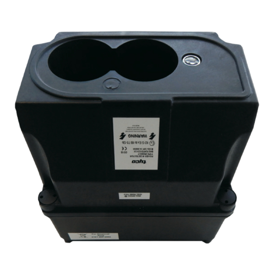
IR6003/7
IR Oil Mist/Smoke
Detector
Contents
1
2
2.1
2.2
3
3.1
3.2
3.3
3.4
4
4.1
4.2
4.2.1 P-UIM
5
5.1
5.2
5.3
Product User Guide
5.4
2
2
2
5.5
2
3
3
6
3
3
7
3
7 .1
7 .2
4
4
8
4
4
9
4
9.1
4
5
5
9.2
6
7
Electrical
Mechanical
Environmental
1 / 12
7
8
8
8
8
9
11
11
11
11
12
12
12
12
12
12
12
12
12
12
Advertisement
Table of Contents

Subscribe to Our Youtube Channel
Related Manuals for Tyco IR6003/7


Summary of Contents for Tyco IR6003/7
-
Page 1: Table Of Contents
1 / 12 IR6003/7 IR Oil Mist/Smoke Detector Product User Guide Contents Flying Lead Connections Introduction 5.4.1 Normal Operation Features 5.4.2 Hazardous Area Operation Detector P-UIM Mounting Details P-UIM 5.5.1 Din Rail Mounting 5.5.2 Screw Mounting Details Functional Description Initialisation... -
Page 2: Introduction
2 / 12 1. Introduction The Tyco Intelligent Oil Mist/Smoke Detector system consists of an IR6003/x Oil Mist/Smoke Detector and a 6005/x Power Universal Interface Module (P-UIM). The Oil Mist/Smoke Detector has been designed to be highly sensitive to the presence of Oil & Kerosene mists or smoke particles in the path of the detector beam. -
Page 3: Functional Description
3 / 12 3. Functional Description 3.1 Initialisation When the detector is switched on the LED indicator flashes briefly to signify power-up. During the first 10-seconds the detector performs auto-calibration to establish the quiescent obscuration level. Note: It is important that the beam path is cleared to a healthy state (no obscuration) prior to resetting the detector. If the beam path is not healthy the detector will recalibrate to the current level of obscuration and may well report false alarm/fault conditions as the path clears. -
Page 4: Indications And Controls
4 / 12 4. Indications and Controls 4.1 Indicators When the detector is switched on the LED indicator flashes briefly to signify power-up. During the first 10-seconds the detector will latch the fault condition and the Detector/P-UIM will require resetting once the beam path is clear. 4.1.1 DETECTOR DETECTOR –... -
Page 5: Installation
5 / 12 5. Installation 5.1 Detector Mounting Details To site the detector, find an unobstructed path, ideally above head height that covers the area to be monitored. When choosing the beam path the direction of any prevailing air currents should be noted to assess the direction that any oil mist would be conveyed. It should be noted that the beam must not be within 500 mm of any wall or partition. -
Page 6: Detector Mounting Bracket
6 / 12 5. Installation 5.2 Detector Mounting Bracket We recommend the use of the 01-33-12, U-Bracket, to mount the IR Detector and to provide alignment facilities. The bracket is supplied with all appropriate hardware to affix the oil mist detector to it. 10 mm clearance required U-Bracket frame RADIAL PIVOT... -
Page 7: Detector Connection Details
7 / 12 5. Installation 5.3 Detector Connection Details 01-33-14 Flying Lead Negative - Wire No 1 Colour - Brown Positive - Wire Colour - Blue Local Junction Box The diagram above shows the detector connected to a local junction box via the flying lead (Part No. 01-33-14). The local junction box will require connecting to the P-UIM, which provides the necessary Detector to user equipment interface. -
Page 8: Normal Operation
8 / 12 5. Installation Brown Neg - Blue Pos + Pin 6 Pin 1 View looking down into the female part of the Flying Lead Plug from the outside When connecting ensure polarity is observed all the way through to the P-UIM, (or via I.S Barrier if used). 5.4.1 Normal Operation (without the use of an I.S Barrier) Positive (+) to P-UIM Terminal 4 (Ballast +) Negative (-) to P-UIM Terminal 6 (Detector -) -
Page 9: Screw Mounting Details
9 / 12 5. Installation 5.5.2 Screw Mounting Details 2-Off M3 tapped 50 mm 85 mm Twist UIM Clockwise 2-Off M3 x 16 mm Mounting screws Screw 2 off M3 x 16 mm long screws 3 mm into the mounting holes. Feed the P-UIM over the mounting screws as shown above and twist clockwise to align. - Page 10 10 / 12 5. Installation 5.6 P-UIM Connection Details 5.6.1 Input Wiring 5.6.2 Output Wiring...
-
Page 11: Commissioning
11 / 12 6. Commissioning Once the Detector has been installed correctly by connecting it to the hazard monitoring system via the P-UIM, the user should power up the detector loop and perform the following confidence checks 1. The Detector LED blips ON briefly as it receives power from the P-UIM. The P-UIM LIFE indicator is flashing and the OUTPUT ON indicator is ON steady all other indicators are extinguished. -
Page 12: Maintenance
12 / 12 8. Maintenance Every 3 months clean the detector lenses and the reflector using warm water and a mild detergent. Dry and polish with a clean soft non-abrasive cloth. Every 3 months after cleaning the detector lenses and reflector test the system using the commissioning procedure as specified in section 6 of this manual.
Need help?
Do you have a question about the IR6003/7 and is the answer not in the manual?
Questions and answers