Table of Contents
Advertisement
Quick Links
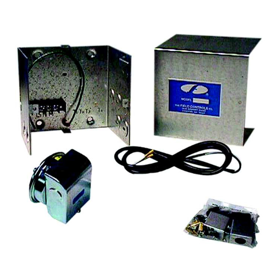
SYSTEM CONTROL KIT
Designed for use with the SWG Series Power Venter for controlling 30-millivolt controlled Natural or LP Gas
appliances with a pressure tap port in the Gas Valve. This kit may also be used with the PVG series sidewall
Power Venters, DI series Draft Inducers, and CAS-4 Combustion Air System. The included junction box is not
required when using a PVG or CAS-4.
ITEMS INCLUDED IN KIT
1- Junction box
1- Fan control gas pressure switch with built in post purge option
1-
1-
1- TCA-1 Thermocouple Adapter
1- 6 ft. length of 12-2 wire
1- 12" jumper wire
1- Flexible conduit connector
2- GSK-3 Spillage Switches
READ THESE INSTRUCTIONS CAREFULLY AND COMPLETELY BEFORE PROCEEDING WITH THE INSTALLATION.
This device MUST be installed by a qualifi ed agency in accordance with the manufacturer's installation instructions. The defi nition of
a qualifi ed agency is: any individual, fi rm, corporation or company which either in person or through a representative is engaged
in, and is responsible for, the installation and operation of HVAC appliances, who is experienced in such work, familiar with all the
precautions required, and has complied with all the requirements of the authority having jurisdiction.
Installed By:
Model: CK-20FV
⁄
" NPT x 3" pipe nipple
1
8
⁄
" NPT pipe tee
1
8
Please retain these instructions after installation.
Phone:
www.fi eldcontrols.com
Installation Date:
P/N 46285000 Rev K 01/18
Advertisement
Table of Contents

Related Manuals for Field Controls CK-20FV


Summary of Contents for Field Controls CK-20FV
- Page 1 SYSTEM CONTROL KIT Model: CK-20FV Designed for use with the SWG Series Power Venter for controlling 30-millivolt controlled Natural or LP Gas appliances with a pressure tap port in the Gas Valve. This kit may also be used with the PVG series sidewall Power Venters, DI series Draft Inducers, and CAS-4 Combustion Air System.
- Page 2 fl exible conduit connector onto a 2" x 4" installer supplied junction box. 2. Fasten the fl exible conduit from the SWG Venter into the conduit connector. Mount the CK-20FV junction box or installer supplied junction box onto the wall or fl oor joist without straining the fl exible conduit. Fasten the CK-20FV junction box through the four dimpled locations on the base of the box.
- Page 3 INSTALLATION OF GAS PRESSURE SWITCH CAUTION: Check gas control valve pressure. Pressure must not exceed 14” WC pressure. 1. Remove pressure tap plug in gas valve. (See Figure 3) NOTE: If installing on an existing appliance, shut off gas supply to gas valve before plug removal.
- Page 4 DRAFT HOOD SAFETY SWITCH INSTALLATION NOTE: 12 ga. wire must be used when wiring safety spillage switches, to reduce the voltage drop in the thermocouple circuit. 1. Remove the thermocouple from the gas control valve. (See Figure 3) 2. Thread the junction block into the thermocouple port and thermocouple into the bottom of the junction block.
- Page 5 WIRING CAUTION: Disconnect electrical power when wiring power venter. Wire the venter motor and controls in accordance with the National Electrical Code, manufacturer’s recommendations and/or applicable local codes. Units must be grounded. Check ground circuit to make certain that the unit has been properly grounded. The wiring should be protected by an overcurrent circuit device rated at 15 amperes.
- Page 6 You will not use the TCA thermocouple adapter, supplied with the CK-20FV. Install the GSK spill switches per instruction and connect to the red wire and the thermal door switch per diagram. Wire the venter motor and controls in accordance with the National Electrical Code, manufacturer’s recommendations and/or applicable local codes.
- Page 7 SYSTEM CONTROL CHECK OUT PROCEDURES: GAS PRESSURE SWITCH FOR WATER HEATER 1. Follow water heater manufacturer’s instructions to light pilot. Turn the gas control valve to the ON position. Adjust the thermostat to call for heat, which will energize the venter motor. (May see a 1 to 8 second delay of venter motor) 2.
- Page 8 This manual may be downloaded and printed from the Field Controls website (www.fi eldcontrols.com) WARRANTY For warranty information about this or any Field Controls product, visit: www.fi eldcontrols.com Field Controls Technical Support 1.800.742.8368 fi eldtec@fi eldcontrols.com Phone: 252.522.3031 • Fax: 252.522.0214 www.fieldcontrols.com...
Need help?
Do you have a question about the CK-20FV and is the answer not in the manual?
Questions and answers