
Related Manuals for McConnel MAGNUM EURO MINI Series


Summary of Contents for McConnel MAGNUM EURO MINI Series
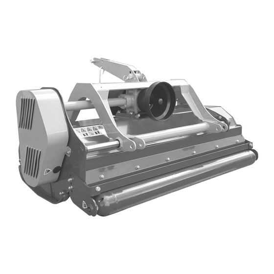
- Page 1 MAGNUM Publication 957 August 2019 Part No. 24214.57 EURO MINI Front / Rear Mounted Shredder Mower Models: 130 / 150 / 185 Operator & Parts Manual...
- Page 2 VERIFICATION OF WARRANTY REGISTRATION DEALER WARRANTY INFORMATION & REGISTRATION VERIFICATION It is imperative that the selling dealer registers this machine with McConnel Limited before delivery to the end user – failure to do so may affect the validity of the machine warranty.
- Page 4 1500 hours. Engine warranty will be specific to the Manufacturer of that unit. 1.02. All spare parts supplied by McConnel Ltd and purchased by the end user are warranted to be free from defects in material and workmanship from the date of sale to the original purchaser for a period of 6 months.
- Page 5 2.02. Any fault must be reported to an authorised McConnel Ltd dealer as soon as it occurs. Continued use of a machine, after a fault has occurred, can result in further component failure for which McConnel Ltd cannot be held liable.
- Page 6 MISCELLANEOUS 4.01. McConnel Ltd may waive compliance with any of the terms of this limited warranty, but no waiver of any terms shall be deemed to be a waiver of any other term. 4.02. If any provision of this limited warranty shall violate any applicable law and is held to be unenforceable, then the invalidity of such provision shall not invalidate any other provisions herein.
- Page 7 DECLARATION OF CONFORMITY Conforming to EU Machinery Directive 2006/42/EC McCONNEL LIMITED, Temeside Works, Ludlow, Shropshire SY8 1JL, UK Hereby declare that: The Product; Tractor Mounted Flail Mower Product Code; MA15 Serial No. & Date ………………………………… Type …………………………...
- Page 8 The inspection sheet on the following page should be kept in this book as a record. A second sheet is included for you to cut out and photocopy or the inspection sheets can be downloaded from our website at; http://www.mcconnel.com/support/aftersales/default.aspx?nav=After Sales...
- Page 10 FLAIL MOWERS PRE-OPERATION Inspection Mower ID ________________ Date: _______________ Shift: _______________ WARNING Before conducting the inspection, make sure the tractor engine is off, with the key removed, all rotation has stopped and the tractor is in park with the parking brake engaged.
- Page 11 TRACTOR PRE-OPERATION Inspection Power Arm ID ________________ Date: _______________ Shift: _______________ WARNING Before conducting the inspection, make sure the tractor engine is off, the key is removed all rotation has stopped and the tractor is in park with the parking brake engaged. Any implement attached to the tractor is firmly on the ground.
- Page 12 FLAIL MOWERS PRE-OPERATION Inspection Mower ID ________________ Date: _______________ Shift: _______________ WARNING Before conducting the inspection, make sure the tractor engine is off, with the key removed, all rotation has stopped and the tractor is in park with the parking brake engaged.
- Page 13 TRACTOR PRE-OPERATION Inspection Power Arm ID ________________ Date: _______________ Shift: _______________ WARNING Before conducting the inspection, make sure the tractor engine is off, the key is removed all rotation has stopped and the tractor is in park with the parking brake engaged. Any implement attached to the tractor is firmly on the ground.
-
Page 14: Table Of Contents
LIST OF CONTENTS Operator Section General Information ......................1 Machine Description & Purpose of Use ................2 Machine Identification ......................2 Technical Information ......................2 Technical Specifications ...................... 3 Safety Information ........................ 4 Safety Decals ........................5 ... -
Page 16: General Information
GENERAL INFORMATION Always read this manual before fitting or operating the machine – whenever any doubt exists contact your dealer or the McConnel Service Department for advice and assistance. Only use ‘Genuine McConnel Parts’ on McConnel machinery and equipment. DEFINITIONS The following definitions apply throughout this manual;... -
Page 17: Machine Description & Purpose Of Use
MACHINE DESCRIPTION & PURPOSE OF USE The Magnum Euro Mini series of machines are ‘3-point linkage’ tractor mounted universal flail mower/shredders designed primarily for the mulching of grasses, brambles, small bushes, branches, vines, and general crop residues. Their tough construction and manual offset capability make them the ideal machines for maintenance use in green areas, vineyards, orchards, verges and scrubland for farmers and contractors alike. -
Page 18: Technical Specifications
TECHNICAL SPECIFICATIONS Magnum Euro Mini Specification 130 Model 150 Model 185 Model Working Width 129cm 145cm 184cm Tractor Power Requirement 24-36 HP 30-40 HP 34-45 HP PTO RPM 540/1000 540/1000 540/1000 Hammer Blades (No. of blades) Y-Blades Option (No. of blades) Machine Weight 281kg 330kg... -
Page 19: Safety Information
SAFETY INFORMATION General safety rules: Always read and follow the instructions for the use and maintenance of the machine before carrying out any work operations or servicing tasks. Improper use of the machine is both highly dangerous to persons and damaging to the machine components –... -
Page 20: Safety Decals
No advice given here can replace ‘good common sense’ and ‘total awareness’ at all times, but will go a long way towards the safe use of your McConnel machine. SAFETY DECALS 1. -
Page 21: Vehicle / Tractor Preparation
VEHICLE / TRACTOR PREPARATION We recommend vehicles are fitted with cabs using ‘safety glass’ windows and protective guarding when used with our machines. Fit Operator Guard (part no. 73 13 324) using the hooks provided. Shape the mesh to cover all vulnerable areas. Remember the driver must be looking through mesh and/or polycarbonate glazing when viewing the machine in all positions - unless the vehicle/ cab manufacturer can... -
Page 22: Attaching Machine
ATTACHING THE MACHINE TO THE TRACTOR Attachment of the machine to the tractor should always be performed on a firm level site. Upper Linkage Position The upper linkage of the machine has two working modes to allow the machine to be mounted on the front or rear of the tractor. - Page 23 PTO Shaft Measurement Measure the PTO shaft and cut to the dimension shown – the finished length of the PTO shaft should be 75mm (3”) less than the measured distance ‘A’ - between tractor shaft and gearbox stub shaft - to enable fitting.
-
Page 24: Setting Up & Adjustment
SETTING UP AND ADJUSTMENT The required height of cut is dependent on working conditions and volume of material. The cutting height can be regulated with the hydraulic system on the tractor and/or rear roller adjustment. The minimum height of cut should be in the region of 1-3 cm. -
Page 25: Drive Belts
DRIVE BELTS Power from the tractor via the machines gearbox and half-shaft is transferred to the rotor through sets of belts - Euro Mini 130 & 150 models employ a 3 belt system and the Euro Mini 185 model employs a 4 belt system. Correct tensioning of the belts is required for both optimal operation of the machine and long lasting belt life –... -
Page 26: Operation
OPERATION Ensure that the operator is suitably qualified to use a machine of this nature and that they have fully read and understood this manual - they should be aware of all safety aspects relating to the safe use of the machine. It is advisable that all ‘first time’ operators practice using the machine in a clear safe area prior to work in order to familiarise themselves with its operation. -
Page 27: Detachment & Storage
DETACHMENT & STORAGE Detaching the machine from the tractor Removal of the machine should be performed on a firm level site. The procedure for detachment is as follows: Place the machine into its central position. Gently lower the machine fully to the ground. ... -
Page 28: Maintenance
MAINTENANCE All maintenance, cleaning and repair operations must be performed with the machine firmly lowered to the ground and detached from the tractor or with the PTO disconnected, engine switched off and starting key removed. For any repairs or maintenance that requires access from underneath, the machine should be firmly and safely raised and propped using suitable purpose designed supports capable of bearing the machines full weight. - Page 29 Gearbox Lubrication The illustrations below show the lubrication access points for the gearbox. Filler plug access A) Filler Plug B) Level Plug C) Drain Plug Lubricant level should be checked on a daily basis prior to work and topped up only when required.
-
Page 30: Troubleshooting
TROUBLESHOOTING PROBLEM POSSIBLE CAUSES REMEDIES Irregular Cut Worn, bent or broken flails Replace flails RPM too low Increase RPM Machine not level to the ground Correct mounting on tractor Clogged material caused by Reduce forward speed excessive forward speed Noise Loose bolts Check and tighten bolts Damaged components... - Page 32 MAGNUM EURO MINI Models: 130 / 150 / 185 Parts Manual...
-
Page 33: Magnum Euro Mini Assembly
MAGNUM EURO MINI ASSEMBLY McCON NEL Models: 130 / 150 / 185... - Page 34 MAGNUM EURO MINI ASSEMBLY McCON NEL Models: 130 / 150 / 185 QUANTITY REF. DESCRIPTION PART No. 9113005 9113006 LOCK NUT 9163004 LOCK NUT 9163005 LOCK NUT 9163006 LOCK NUT 9163010 LOCK NUT 9163008 FLAT WASHER 9100104 FLAT WASHER 9100105 FLAT WASHER 9100106 FLAT WASHER...
- Page 35 MAGNUM EURO MINI ASSEMBLY McCON NEL Models: 130 / 150 / 185...
- Page 36 MAGNUM EURO MINI ASSEMBLY McCON NEL Models: 130 / 150 / 185 QUANTITY REF. DESCRIPTION PART No. BELT 1061609 BUSH 1061138 CIRCLIP 1061242 HYDRAULIC RAM (Hydraulic Offset Models) 1062406 HYDRAULIC RAM (Hydraulic Offset Models) 1062407 BOLT 9213186 GREASE NIPPLE EXTENSION 1061558 PVC CAP 1062046...
- Page 37 MAGNUM EURO MINI ASSEMBLY McCON NEL Models: 130 / 150 / 185...
- Page 38 MAGNUM EURO MINI ASSEMBLY McCON NEL Models: 130 / 150 / 185 QUANTITY REF. DESCRIPTION PART No. PIVOT PIN 1062436 PIVOT PIN 1062437 LINKAGE PIN 1062438 BUSH 1062272 BEARING 1062273 WASHER 1062274 WASHER 1062275 POSITION BAR (Manual offset models) 1062439 PTO HOOK 1062393 WASHER...
- Page 40 McConnel Limited, Temeside Works, Ludlow, Shropshire SY8 1JL. England. Telephone: 01584 873131. Facsimile: 01584 876463. www.mcconnel.com...
Need help?
Do you have a question about the MAGNUM EURO MINI Series and is the answer not in the manual?
Questions and answers