Lochinvar Crest 2.5 Installation & Operation Manual
Condensing boiler
Hide thumbs
Also See for Crest 2.5:
- Service manual (56 pages) ,
- Supplemental manual (20 pages) ,
- Installation instructions (2 pages)
Table of Contents
Advertisement
Quick Links
FB-I-O Rev I
Installation & Operation Manual
Models: 1.5 - 2.0 - 2.5 - 3.0 - 3.5
This manual must only be used by
WARNING
a qualified heating installer / service
technician. Read all instructions,
including this manual and the Crest
Service Manual, before installing.
Perform steps in the order given.
Failure to comply could result in
severe personal injury, death, or
substantial property damage.
Save this manual for future reference.
Advertisement
Table of Contents

Related Manuals for Lochinvar Crest 2.5


Summary of Contents for Lochinvar Crest 2.5
- Page 1 FB-I-O Rev I Installation & Operation Manual Models: 1.5 - 2.0 - 2.5 - 3.0 - 3.5 This manual must only be used by WARNING a qualified heating installer / service technician. Read all instructions, including this manual and the Crest Service Manual, before installing.
-
Page 2: Table Of Contents
Contents HAZARD DEFINITIONS ............ 2 5. HYDRONIC PIPING PLEASE READ BEFORE PROCEEDING ......3 System Water Piping Methods ......... 24 THE CREST -- HOW IT WORKS ........4-5 Low Water Cutoff Device ..........24 RATINGS ................6 Chilled Water System ............24 Freeze Protection ............. -
Page 3: Please Read Before Proceeding
Installation & Operation Manual Please read before proceeding When servicing boiler – Installer – Read all instructions, including WARNING this manual and the Crest Service Manual, • To avoid electric shock, disconnect electrical supply before installing. Perform steps in the before performing maintenance. -
Page 4: The Crest - How It Works
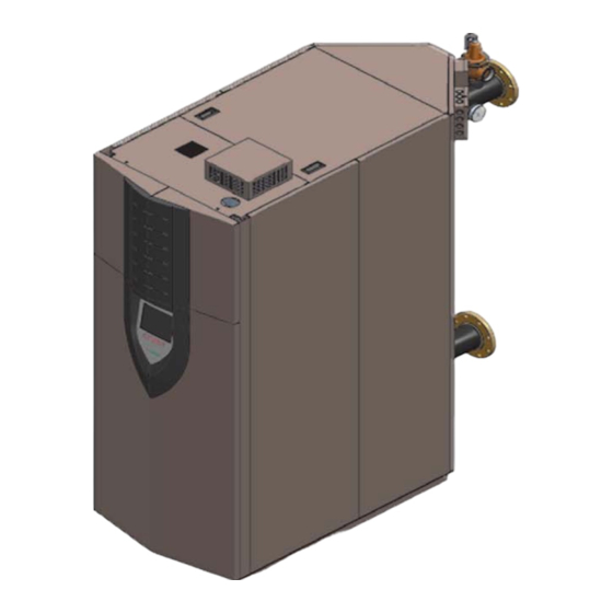
Installation & Operation Manual The Crest - How it works... 19. High limit devices (primary and backup) Front access panels The high limit devices are used to monitor the outlet water Provides access to the controls compartment. temperature - if either device senses the water temperature Top access panel exceeding the predetermined setting, the boiler will shut down. - Page 5 Installation & Operation Manual The Crest - How it works... (continued) Models 1.5 - 2.0 - 2.5 - 3.0 - 3.5 Front View Rear View Right Side (inside unit) Left Side (inside unit)
-
Page 6: Ratings
Installation & Operation Manual Ratings Crest Other Specifications AHRI Rating Vent Weight AHRI Model Number Gross Input Appliance Size w/Water Pipe Pipe Ratings Output Water Gas Inlet (lbs.) Size Size Size Water, Content Size Outlet Inlet Note: Change “N” to (Note 4) Gallons “L”... -
Page 7: Determine Boiler Location
Installation & Operation Manual Determine boiler location Installation must comply with: This appliance is certified as an indoor appliance. WARNING Do not install the appliance outdoors or locate • Local, state, provincial, and national codes, laws, where the appliance will be exposed to freezing regulations, and ordinances. -
Page 8: Provide Air Openings To Room
Installation & Operation Manual Determine boiler location Provide air openings to room: Vent and air piping The Crest requires a special gas vent system, designed for The Crest alone in boiler room pressurized venting. 1. No air ventilation openings into the boiler room are The boiler is to be used for either direct vent installation or needed when clearances around the Crest are at least for installation using indoor combustion air. -
Page 9: Using An Existing Vent System To Install A New Boiler
Installation & Operation Manual Determine boiler location (continued) When using an existing vent system to install a new boiler: Table 1A Corrosive Contaminants and Sources Products to avoid: Failure to follow all instructions can result WARNING in flue gas spillage and carbon monoxide Spray cans containing chloro/fluorocarbons emissions, causing severe personal injury Permanent wave solutions... -
Page 10: Removing A Boiler From Existing Common Vent
Installation & Operation Manual Determine boiler location When removing a boiler from existing common vent system: Do not install the Crest into a common d. Place in operation the appliance being inspected. DANGER vent with any other appliance except Follow the lighting instructions. Adjust thermostat so as noted in Section 2 on page 18. -
Page 11: Remove Boiler From Wood Pallet
Installation & Operation Manual Determine boiler location (continued) Remove boiler from wood pallet Figure 1-3 Boiler Removed from Shipping Pallet After removing the outer shipping crate and plastic from the boiler, remove the parts package (packaged parts inside the controls compartment of the boiler inside the lower front access panel). -
Page 12: Combustion And Ventilation Air Requirements
Installation & Operation Manual Determine boiler location Combustion ventilation requirements for appliances drawing air from the equipment room Provisions for combustion and ventilation air must be in accordance with Air for Combustion and Ventilation, of the latest edition of the National Fuel Gas Code, NFPA 54 / ANSI Z223.1, in Canada, the latest edition of CGA Standard B149 Installation Code for Gas Burning Appliances and Equipment, or applicable provisions of the local building codes. - Page 13 Installation & Operation Manual Determine boiler location (continued) Under no circumstances should the If a single combustion air opening is provided to bring CAUTION equipment room ever be under negative combustion air in directly from the outdoors, the pressure. Particular care should be taken opening must be sized based on a minimum free area where exhaust fans, attic fans, clothes dryers, of one square inch per 3000 Btu/hr (7 cm...
-
Page 14: General Venting
Installation & Operation Manual General venting Direct venting Sidewall Vertical Vent, Sidewall Air Vertical Optional room air Vertical Sidewall... -
Page 15: Install Vent And Combustion Air Piping
Installation & Operation Manual General venting (continued) Install vent and combustion air piping The Crest must be vented and supplied Sealing of Type “B” double-wall vent material or galvanized DANGER with combustion and ventilation air as vent pipe material used for air inlet piping on a sidewall or described in this section. -
Page 16: Vent And Air Piping
Installation & Operation Manual General venting Air intake/vent connections When a sidewall or vertical rooftop combustion air supply system is disconnected for any reason, the air inlet pipe must Combustion Air Intake Connector (FIG. 2-1) - Used to be resealed to ensure that combustion air will be free of provide combustion air directly to the unit from outdoors. -
Page 17: Min./Max. Combustion Air & Vent Piping Lengths
Installation & Operation Manual General venting (continued) Table 2B Direct Vent Minimum / Maximum Allowable Air / Vent Lengths AIR INLET VENT Input Model De-Rate per Air Intake Air Intake Air Intake Vent Vent Vent 25 feet of Vent Diameter Min. -
Page 18: Common Venting
Crest boilers connected to the common vent must all be FB2000 8" DRH30001 of the same size. FB2500 9" DRH30002 Each Crest boiler must have a Lochinvar supplied flue FB3000 10" DRH30003 damper installed (see Table 2D). FB3500 10" DRH30003... -
Page 19: Vertical Direct Venting Vent/Air Termination - Vertical
Installation & Operation Manual Vertical direct venting Vent/air termination – vertical Follow instructions below when determining WARNING Figure 3-2 Vertical Termination of Air and Vent w/Rain vent location to avoid possibility of severe personal injury, death or substantial property damage. Do not connect any other appliance to the WARNING vent pipe or multiple boilers to a common... -
Page 20: Multiple Vent/Air Terminations
Installation & Operation Manual Vertical direct venting 3. The vent piping must terminate in an up-turned coupling Figure 3-4 Alternate Vertical Terminations with Multiple as shown in FIG. 3-1. The top of the coupling or the Boilers rain cap must be at least 36" (914 mm) above the air intake. -
Page 21: Sidewall Direct Venting Vent/Air Termination - Sidewall
Installation & Operation Manual Sidewall direct venting Vent/air termination – sidewall Follow instructions below when Sidewall vent and air inlet terminations WARNING WARNING determining vent location to avoid must terminate in the same pressure possibility of severe personal injury, death, zone. -
Page 22: Prepare Wall Penetrations
Installation & Operation Manual Sidewall direct venting Vent/air termination – sidewall Prepare wall penetrations Figure 4-2 Clearance to Doors and Windows Air pipe penetration: Cut a hole for the air pipe. Size the air pipe hole as close as desired to the air pipe outside diameter. -
Page 23: Room Air
Installation & Operation Manual Sidewall direct venting (continued) 2. Place wall penetrations to obtain minimum clearance Figure 4-6 Room Air (Direct Exhaust Terminations) of 12 inches (305 mm) between vent pipe and adjacent air inlet, as shown in FIG. 4-4 for U.S. installations. For ROOM AIR (DIRECT EXHAUST TERMINATIONS) Canadian installations, provide clearances required by Vent Termination... -
Page 24: Hydronic Piping
Installation & Operation Manual Hydronic piping System water piping methods General piping information The Crest is designed to function in a closed loop pressurized Basic steps are listed below along with illustrations on the system not less than 12 psi (83 kPa). A temperature and following pages, which will guide you through the installation pressure gauge is included to monitor system pressure and of the Crest (5-2 thru 5-5). -
Page 25: Circulator Sizing
Installation & Operation Manual Hydronic piping (continued) Circulator sizing The Crest heat exchanger does have a pressure drop, which must be considered in your system design. Refer to the graph in FIG. 5-1 for pressure drop through the Crest heat exchanger. Figure 5-1 Pressure Drop vs. -
Page 26: Near Boiler Piping Components
ASME specifications. MODEL FLOW RATE (GPM) 9. System temperature sensor: FB(N,L)1500 Lochinvar supplies a system temperature sensor. FB(N,L)2000 The sensor is to be installed in the heating loop downstream from the boiler hot water piping and FB(N,L)2500 heating loop junction. - Page 27 Installation & Operation Manual Hydronic piping (continued) Figure 5-2 Single Boiler - Recommended - Primary / Secondary Piping with a Hot Water Generator FROM SYSTEM SYSTEM RETURN SENSOR 12" BALL VALVE RELIEF HOT WATER (TYPICAL) VALVE GENERATOR AIR SEPERATOR DRAIN PORT (TYPICAL) SYSTEM SUPPLY SENSOR...
- Page 28 Installation & Operation Manual Hydronic piping Table 5C Multiple Boilers - Common Header - Primary / Secondary Flow Number of Units Model Recommended Common Header Pipe Sizes in Inches FB 1500 FB 2000 FB 2500 FB 3000 FB 3500 [Based on a boiler ΔT of 30°F.] A system supply sensor (factory supplied) MUST BE installed for proper boiler operation.
- Page 29 Installation & Operation Manual Hydronic piping (continued) Figure 5-4 Single Boiler - Alternate - Fixed or Variable Flow Primary System Piping RELIEF VALVE BALL VALVE (TYPICAL) FROM SYSTEM AIR SEPERATOR BOILER DRAIN DRAIN PORT (TYPICAL) SYSTEM CIRCULATOR Y-STRAINER (RECOMMENDED) EXPANSION TANK TO SYSTEM PRESSURE...
- Page 30 Installation & Operation Manual Hydronic piping Figure 5-5 Multiple Boilers - Alternate - Common Header - Fixed or Variable Flow Primary RELIEF VALVE (TYPICAL) BALL VALVE (TYPICAL) FROM SYSTEM BOILER DRAIN (TYPICAL) SYSTEM RETURN AIR SEPERATOR SENSOR DRAIN PORT (TYPICAL) SYSTEM SUPPLY SENSOR SYSTEM...
-
Page 31: Gas Connections Connecting Gas Supply Piping
Installation & Operation Manual Gas connections Connecting gas supply piping 3. Purge all air from the gas supply piping. For dual fuel models, reference the Crest NOTICE Dual Fuel Supplemental Manual. 4. Before placing the boiler in operation, check the boiler and its gas connection for leaks. -
Page 32: Natural Gas
Installation & Operation Manual Gas connections Natural gas supply pressure requirements Use two wrenches when tightening gas WARNING piping at boiler (FIG. 6-2), using one 1. Pressure required at the gas valve inlet pressure port: wrench to prevent the boiler gas line •... -
Page 33: Check Inlet Gas Supply
Installation & Operation Manual Gas connections (continued) Table 6B Natural Gas Pipe Size Chart TABLE - 6B GAS PIPING SIZE CHART Nominal Maximum Length of Pipe in Straight Feet Capacity of Pipe Iron Pipe in Thousands Size of Btu/hr for Inches gas pressures of 14 Inches Water... -
Page 34: Gas Pressure
Installation & Operation Manual Gas connections Gas Pressure Do not check for gas leaks with an open WARNING flame -- use the bubble test. Failure to The gas pressure must remain between 4 inches w.c. use the bubble test or check for gas leaks (.99 kPa) minimum and 14 inches w.c. -
Page 35: Field Wiring
Installation & Operation Manual Field wiring Installation must comply with: ELECTRICAL SHOCK HAZARD – For WARNING your safety, turn off electrical power supply before making any electrical connections 1. National Electrical Code and any other national, state, to avoid possible electric shock hazard. provincial, or local codes, or regulations. -
Page 36: Low Voltage Connections
Installation & Operation Manual Field wiring Low voltage connections ModBus The RS-485 ModBus cable is connected to the ModBus 1. Route all low voltage wires through the knockouts in the terminals. Use shielded, 2-wire twisted pair cable. If desired, rear of the boiler, as shown in FIG. 7-2. the shield can be connected to ground by installing a jumper 2. -
Page 37: Wiring Of The Cascade
Installation & Operation Manual Field wiring (continued) Auxiliary switch 1 & 2 Wiring of the cascade Additional field supplied limit controls may be connected to When wiring the boilers for Cascade operation, select one boiler the auxiliary switch inputs. If additional limit controls fail or as the Leader boiler. - Page 38 Installation & Operation Manual Field wiring Figure 7-3 Low Voltage Field Wiring Connections...
-
Page 39: Condensate Disposal Condensate Drain
Installation & Operation Manual Condensate disposal Condensate drain 9. Do not expose condensate line to freezing temperatures. 1. The Crest is a high efficiency appliance that produces Use materials approved by the authority condensate. NOTICE having jurisdiction. In the absence of 2. -
Page 40: Startup
Installation & Operation Manual Start-up Check/control water chemistry Fill and test water system Do not use petroleum-based cleaning or CAUTION sealing compounds in the boiler system. 1. Fill system only after ensuring the water meets the Damage to elastomer seals and gaskets requirements of this manual. -
Page 41: Check For Gas Leaks
Installation & Operation Manual Start-up (continued) Check for gas leaks Propane boilers only – Your propane WARNING supplier mixes an odorant with the propane Before starting the boiler, and during to make its presence detectable. In some WARNING initial operation, smell near the floor and instances, the odorant can fade, and the around the boiler for gas odorant or any gas may no longer have an odor. -
Page 42: Start The Boiler
Installation & Operation Manual Start-up Final checks before starting the boiler Check vent piping and air piping 1. Check for gastight seal at every connection, seam of air Read the Crest Service Manual to familiarize yourself piping, and vent piping. with SMART TOUCH control module operation. -
Page 43: For Your Safety Read Before Operating
Installation & Operation Manual Start-up (continued) Figure 9-2 Operating Instructions FOR YOUR SAFETY READ BEFORE OPERATING WARNING: If you do not follow these instructions exactly, a fire or explosion may result causing property damage, personal injury, or loss of life. •... -
Page 44: Set Space Heating Operation
Installation & Operation Manual Start-up Check flame and combustion Set space heating operation (continued) 4. Navigate to the Service Screen from the Home Screen by Verify space heat circulator mode pressing the MAIN MENU button and then the SERVICE The system pump output can be programmed to never button. - Page 45 Installation & Operation Manual Start-up (continued) Set Hot Water Generator (HWG) operation Verify HWG circulator mode The internal clock does not adjust for The HWG Mode is programmed to heat an indirect hot NOTICE Daylight Savings Time and therefore, will water tank.
-
Page 46: Operating Information
Installation & Operation Manual Operating information General HWG priority The SMART TOUCH control module allows connection of a How the boiler operates HW thermostat or sensor to the low voltage connection board. When the HW thermostat or sensor calls for heat, the control The Crest uses an advanced stainless steel heat exchanger module activates the HW pump, shuts down the boiler pump, and electronic control module that allows fully condensing... - Page 47 Installation & Operation Manual Operating information (continued) Ramp Delay Gradient limiting If during operation of the boiler the outlet water temperature For systems with lower flow, the SMART TOUCH can limit is rising too quickly, the control will reduce the firing rate to the firing rate (when enabled) when a space heating call for its lowest setting.
- Page 48 Installation & Operation Manual Operating information Monitor external limits High limit operations Connections are provided on the connection board for The Crest SMART TOUCH control has two (2) integral limits, external limits such as an additional high limit. one auto reset and one manual reset. The Crest also has one SMART TOUCH control will shut off the burner and auxiliary manual reset high limit.
-
Page 49: Cascade
Installation & Operation Manual Operating information (continued) Cascade Sequence of the cascade When multiple boilers are installed, they can be wired together To equalize the run time of all boilers on the Cascade, the in a cascade sequence. A maximum of eight boilers can be firing sequence will automatically be changed at set intervals. -
Page 50: Sequence Of Operation
Installation & Operation Manual Operating information Sequence of operation Note: This unit is equipped with two (2) gas train systems. Gas Train 1 will fire first. If the demand cannot be met by the first gas train, the second gas train (Gas Train 2) will fire. Upon a call for heat, the control turns on the appropriate pumps (system and boiler pumps for a space heating call, HW pump for a domestic hot water call). -
Page 51: Status Screen
Installation & Operation Manual Operating information (continued) Crest control module The Home Screen displays status, modulation rate, outlet water temperature, inlet water temperature, flue temperature, system supply temperature, system return temperature, outdoor air temperature, and domestic hot water tank temperature. The boiler can be started and stopped by pressing the ON/OFF button. -
Page 52: Main Screen
Installation & Operation Manual Operating information Use the Main Menu Screen (FIG. 10-2) to access the screens necessary to set temperatures, operating conditions, and monitor boiler operation. The Crest is equipped with a SMART TOUCH control system. All menu options are accessed by touching the screen with your finger or a stylus from a PDA. -
Page 53: Maintenance
Installation & Operation Manual Maintenance Maintenance and annual startup Table 11A Service and Maintenance Schedules Owner maintenance Service technician (see the Crest User’s Information Manual for (see the following pages for instructions) instructions) General: • Address reported problems, if any •... -
Page 54: Address Reported Problems
Installation & Operation Manual Maintenance Follow the service and maintenance procedures given throughout this manual and in component literature WARNING shipped with the boiler. Failure to perform the service and maintenance could result in damage to the boiler or system. Failure to follow the directions in this manual and component literature could result in severe personal injury, death, or substantial property damage. -
Page 55: Check Expansion Tank
Installation & Operation Manual Maintenance (continued) Flue vent system and air piping Safety relief valves should be re-inspected WARNING AT LEAST ONCE EVERY THREE YEARS, Visually inspect the entire flue gas venting system and air by a licensed plumbing contractor or piping for blockage, deterioration or leakage. -
Page 56: Check Control Settings
Installation & Operation Manual Maintenance Inspect ignition flame • Shut down the boiler: sense electrodes - Follow the “To Turn Off Gas to Appliance” instructions for the boiler in Section 9 - Startup. 1. Remove the ignition and both flame sense electrodes - Do not drain the boiler unless it will be exposed to from the burner plate. -
Page 57: Review With Owner
Installation & Operation Manual Maintenance (continued) Review with owner 15. Replace the burner mounting plate assembly and gas/air manifold assembly. Ensure gaskets are in good condition 1. Review the Crest User’s Information Manual with the and positioned properly. Restore boiler to operation. owner. -
Page 58: Diagrams
Installation & Operation Manual Diagrams Figure 12-1 Ladder Diagram... -
Page 59: Wiring Diagram
Installation & Operation Manual Diagrams (continued) Figure 12-2 Wiring Diagram... -
Page 60: Revision Notes
Revision Notes: Revision A (ECO #C07970) initial release. Revision B (ECO #C08023) reflects changes made to FIG. 6-3 on page 32 for Mass approval and changes made to FIG. 5-3 on page 28. Revision C (ECO #C08179) reflects the addition of three (3) new vent manufacturers (pg.
Need help?
Do you have a question about the Crest 2.5 and is the answer not in the manual?
Questions and answers