CMOSTEK CMT2150A User Manual
One-way rf link development kits
Hide thumbs
Also See for CMT2150A:
- Design manual (12 pages) ,
- User manual (34 pages) ,
- Manual (31 pages)
Table of Contents
Advertisement
Quick Links
CMT2150A/2250(1)A One-Way RF Link Development Kits User's Guide
Introduction
The purpose of this document is to provide the guidelines for the users to use the CMT2150A/2250(1)A One-Way RF Link
Development Kits (Development Kits) in different application schemes. The related part numbers covered by this document is
shown in table below.
Part Number
True single-chip, highly flexible, high performance, OOK RF transmitter with embedded data encoder
CMT2150A
ideal for 240 to 480 MHz wireless applications
True single-chip, ultra low power and high performance device that consists of an OOK RF receiver, a
CMT2250A
data decoder and 4 data output pins for various 300 to 480 MHz wireless applications
True single-chip, ultra low power and high performance device that consists of an OOK RF receiver, a
CMT2251A
data decoder and 1 PWM output pin for various 300 to 480 MHz wireless applications.
The Development Kits are a set of the hardware and software tools designed to help the users to easily evaluate the
performance and demonstrate the features of products CMT2150A, CMT2250A and CMT2251A. These devices are part of the
CMOSTEK Microelectronics Co., Ltd. (CMOSTEK) NextGenRF
receivers and transceivers. They are optimized for the low system cost, low power consumption, battery-powered one-way RF
link application with their highly integrated and low power design.
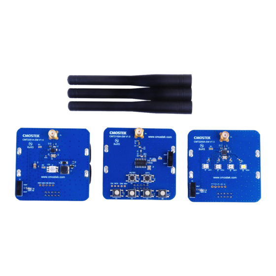
The package of the Development Kits is shown in Figure 1.
Figure 1. CMT2150A/2250(1)A One-Way RF Link Development Kits
Copyright © By CMOSTEK
Table 1. Part Numbers Covered in this Document
Rev 1.0 | Page 1 / 34
Description
TM
family, which includes a complete line of transmitters,
AN113
AN113
www.cmostek.com
Advertisement
Table of Contents

Related Manuals for CMOSTEK CMT2150A


Summary of Contents for CMOSTEK CMT2150A
- Page 1 CMT2150A/2250(1)A One-Way RF Link Development Kits User’s Guide Introduction The purpose of this document is to provide the guidelines for the users to use the CMT2150A/2250(1)A One-Way RF Link Development Kits (Development Kits) in different application schemes. The related part numbers covered by this document is shown in table below.
-
Page 2: Table Of Contents
7.4 Burn Log................................28 7.5 Read Device ................................ 29 8. Frequently Asked Questions ............................ 30 9. Document Change List.............................. 31 10. Appendix: CMT2150A-EM and CMT2250(1)A-EM Schematics ................32 11. Contact Information ..............................34 Rev 1.0 | Page 2 / 34 www.cmostek.com... - Page 3 Evaluation Module(s) Radio Frequency Error RFPDK RF Products Development Kit Identification Receiving, Receiver ksps Kilo Symbols Per Second Transmission, Transmitter Light Emitting Diode Symbol Rate On-Off Keying Universal Serial Bus Power Amplifier Rev 1.0 | Page 3 / 34 www.cmostek.com...
-
Page 4: Development Kits Contents
Please note that the CMT2150A-EM is by default configured to work in pair with CMT2250A-EM. Using the RFPDK, the user can easily program the PWM function into the CMT2150A, so that it can work in pair with CMT2251A-EM. Please refer to “Chapter 2 Application Schemes”... - Page 5 AN113 CMT2150A-EM The CMT2150A-EM is the Tx evaluation module, it can be used to work in pair with CMT2250A-EM to demonstrate the On-Off control feature, and work in pair with CMT2251-EM to demonstrate the PWM control feature. CMT2250A-EM The CMT2250A-EM is the On-Off control Rx evaluation module.
-
Page 6: Application Schemes
2. Application Schemes In order to help to user to start using the Development Kits easily, CMOSTEK has defined a few configurations with different application schemes on the RFPDK. The user only needs to follow the guidelines in the subsections of this chapter, program the configuration to the corresponding evaluation modules and start the evaluation. -
Page 7: Led On/Off
In the LED On/Off scheme, the user can experience to push buttons on the transmitter module to turn on and off the LEDs on the receiver module. Push buttons on the CMT2150A-EM and the 4 LEDs on CMT2250A-EM are shown and described as below. -
Page 8: Pulse
= Pin11 (K1) Notes: Please refer to the “AN112 CMT2150A Configuration Guideline” for the introduction of Toggle mode of the push button setting and the 1920 encoding format. The study function is enabled in this scheme, while the Sync ID on both of the Tx and Rx side are set to the same by default. - Page 9 USB cable, then start the RFPDK on the PC. Connect the CMT2150A-EM to the USB Programmer with EM-Connector, select CMT2150A on the RFPDK, stay in Basic Mode, select the Pulse configuration on the configuration list, as shown in figure below, and burn the configuration to the CMT2150A-EM.
-
Page 10: Periodic Tx
2.3 Periodic Tx In the Periodic Tx scheme, the CMT2150A-EM will send out packets to the CMT2250A-EM automatically in every 3 seconds. The LED1-3 on the CMT2250A-EM will be turned on for 500 ms on each transmission. The push buttons are shown and described in the figure/table below: Rev 1.0 | Page 10 / 34... - Page 11 USB cable, then start the RFPDK on the PC. Connect the CMT2150A-EM to the USB Programmer with EM-Connector, select CMT2150A on the RFPDK, select the Advanced Mode, select the Periodic configuration on the configuration list, as shown in figure below, and burn the configuration to the CMT2150A-EM.
-
Page 12: Pwm
2.4 PWM In the PWM scheme, the user can use the push buttons on the CMT2150A-EM to perform dimming control on the LED on the CMT2251A-EM by the PWM signals generated by CMT2251A. The brightness of the LED changes with the duty cycle of the PWM signal. - Page 13 USB cable, then start the RFPDK on the PC. Connect the CMT2150A-EM to the USB Programmer with EM-Connector, select CMT2150A on the RFPDK, select the Advanced Mode, select the PWM configuration on the configuration list, as shown in figure below, and burn the configuration to the CMT2150A-EM.
-
Page 14: Normal
The user can experience the normal scheme, by setting the Button Mode on the RFPDK to Normal. In this scheme, each LED on the CMT2250A-EM is controlled by one push button on the CMT2150A-EM respectively. The push buttons are shown and described in the figure/table below: Figure 16. - Page 15 Proper configuration of the Data Pin Reset Code for the CMT2250A-EM is required if the user wants to turn off all the LEDs at the same time. For example, if the Data Pin Reset Code is set to D0:D3 = 0100, K1 on the CMT2150A-EM becomes the Off button to turn off all the LEDs on the CMT2250A-EM.
- Page 16 AN113 Figure 18. Configuring Data Pin Reset Code of the CMT2250A The user can refer to “AN112 CMT2150A Configuration Guideline” for more information about the Normal button mode. Rev 1.0 | Page 16 / 34 www.cmostek.com...
-
Page 17: Cmt2150A-Em
3. CMT2150A-EM The CMT2150A-EM is the Tx module with a CMT2150A device, 6 push buttons, battery case and a couple of necessary external components. The EM-Connector on the back side of the module allows the connection to the USB Programmer. The main components are listed below: Figure 19. - Page 18 The evaluation module contained in this Development Kits is designed with the matching network at 433.92 MHz. For application with different frequencies, the matching network might need to be changed. See “Chapter 10 Appendix: CMT2150A-EM and CMT2250(1)A-EM Schematics” for the CMT2150A-EM Schematic. Rev 1.0 | Page 18 / 34...
-
Page 19: Cmt2250A-Em
LED – 4 orange LEDs are available on the PCB connecting the pins DATA0 – DATA3. The LEDs are lighted up according to different button modes selected at the Tx side to demonstrate the functions of the CMT2150A and CMT2250A. - Page 20 AN113 The module can work with CMT2150A-EM to demonstrate the Normal, Toggle and Matrix button modes and periodic transmission. The evaluation module contained in this Development Kits is designed with the matching network at 433.92 MHz. For application with different frequencies, the matching network might need to be changed.
-
Page 21: Cmt2251A-Em
LED when there is PWM signal coming out from the CMT2251A to adjust the brightness of the LED. The definition of the EM-connector on the CMT2251A-EM is given below: Signal Name Figure 25. EM-Connector on the Table 13. CMT2251A-EM EM-Connector Pin Definition CMT2251A-EM Rev 1.0 | Page 21 / 34 www.cmostek.com... - Page 22 AN113 The module can work with CMT2150A-EM to demonstrate the Normal, Toggle and Matrix button modes and periodic transmission. The evaluation module contained in this Development Kits is designed with the matching network at 433.92 MHz. For application with different frequencies, the matching network might need to be changed.
-
Page 23: Usb Programmer
6. USB Programmer The USB Programmer is the programming tool for the user to program the configuration into the CMOSTEK NextGenRF products with the RFPDK. The evaluation modules should be connected to the PC through the USB Programmer. There are 3 LEDs on the USB Programmer to indicate its working status. -
Page 24: Usb Socket
USB Programmer to the PC. The USB socket has two functions: Obtain power from the PC to supply the USB Programmer. Communicate to the RFPDK installed on the PC. Figure 28. USB Socket Rev 1.0 | Page 24 / 34 www.cmostek.com... -
Page 25: Rfpdk
AN113 7. RFPDK RFPDK (RF Products Development Kit) is a member of the CMT2150A/2250(1)A One-Way RF Link Development Kits supporting the development and manufacturing with CMOSTEK NextGenRF products. It is a PC application runs on Windows 2000, XP, 7 and 8. It works with the USB Programmer to configure the CMOSTEK NextGenRF products. - Page 26 AN113 Figure 31. Device Selection Panel Select the proper device, and then click “Next”, the Device Control Panel appears as below. Figure 32. Device Control Panel Rev 1.0 | Page 26 / 34 www.cmostek.com...
-
Page 27: Device Control Panel
It lets the users to select predefined chip configuration from the list, including the default configurations provided by CMOSTEK or the customized configurations save by the user. For the non-default configurations, the user can add notes to the “List Type” column by double-clicking the cell, as shown in the below figure. -
Page 28: Status And Notice
The USB Programmer is properly connected to the PC. USB: Unconnected The USB Programmer is unconnected or improperly connected to the PC. Device: CMT2150A The device is properly connected to the USB Programmer. The device is unconnected or improperly connected to the USB Programmer, or the device is Device: Unknown connected but the USB Programmer is in “Unconnected”... -
Page 29: Read Device
The user can save the Burn Log to a text file by pressing the Save button. This text file is one of the necessary materials to send back to CMOSTEK when the user asks for any technical support. 7.5 Read Device When the device, the USB Programmer and the PC (RFPDK) are properly connected, the Read Device function can be used to read out and upload the EEPROM contents from the device to the PC. -
Page 30: Frequently Asked Questions
Q4. Can the RFDPK and the USB Programmer support all CMOSTEK RF products? A4. The current version of RFPDK and USB Programmer supports the existing RF products. In the future, CMOSTEK will update the RFPDK and USB Programmer firmware to support the new products. The user can visit www.cmostek.com... -
Page 31: Document Change List
AN113 9. Document Change List Table 18. Document Change List Rev. No Chapter Description of Changes Date Initial version 2014-08-13 Rev 1.0 | Page 31 / 34 www.cmostek.com... -
Page 32: Appendix: Cmt2150A-Em And Cmt2250(1)A-Em Schematics
AN113 10. Appendix: CMT2150A-EM and CMT2250(1)A-EM Schematics Figure 35. CMT2150A-EM Schematic Figure 36. CMT2250A-EM Schematic Rev 1.0 | Page 32 / 34 www.cmostek.com... - Page 33 AN113 Figure 37. CMT2251A-EM Schematic Rev 1.0 | Page 33 / 34 www.cmostek.com...
-
Page 34: Contact Information
The material contained herein is the exclusive property of CMOSTEK and shall not be distributed, reproduced, or disclosed in whole or in part without prior written permission of CMOSTEK. CMOSTEK products are not authorized for use as critical components in life support devices or systems without express written approval of CMOSTEK.
Need help?
Do you have a question about the CMT2150A and is the answer not in the manual?
Questions and answers