Table of Contents
Advertisement
Quick Links
CMT2250A Configuration Guideline
Introduction
The purpose of this document is to provide the guidelines for the users to configure the CMT2250A on the RFPDK. The part
number covered by this document is shown in the table below.
Part Number
True single-chip, ultra low power and high performance device that consists of an OOK RF receiver, a
data decoder and 4 data output pins for various 300 to 480 MHz wireless applications. The decoder
CMT2250A
supports 1920, 1527 and 2262 packet formats. The chip is part of the CMOSTEK NextGenRF
which includes a complete line of transmitters, receivers and transceivers.
The RFPDK (Radio Frequency Products Development Kit) is a PC application developed by CMOSTEK for the NextGenRF
product line. Differing from traditional RF chip configuration methods, which usually require complex software programming and
register-based controlling, the RFPKD revolutionarily simplifies the NextGenRF
complete the product configuration by just clicking and inputting a few parameters. After that, the product can be directly used in
the RF system without performing any further configurations.
To help the user to develop their application with CMT2150A and CMT2250(1)A easily, CMOSTEK provides
CMT2150A/2250(1)A One-Way RF Link Development Kits that enables the user to quickly evaluate the performance,
demonstrate the features and develop the application. The Development Kits includes:
RFPDK
USB Programmer
CMT2150A-EM (Tx module)
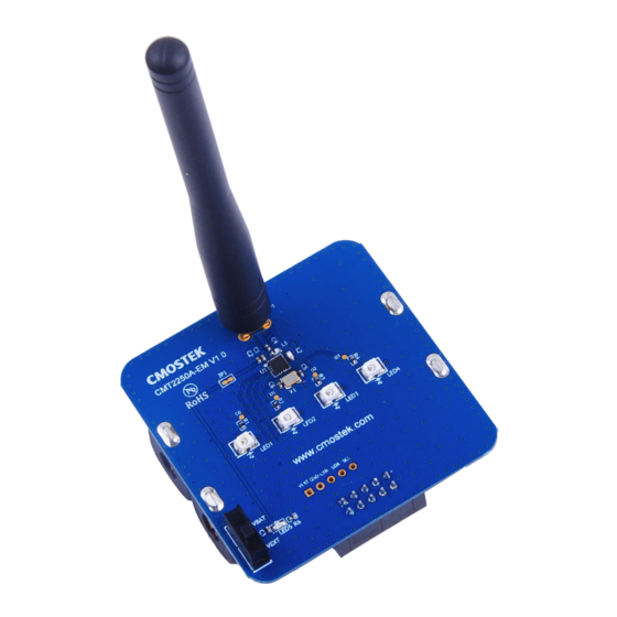
CMT2250A-EM (Rx on-off control module)
CMT2251A-EM (Rx PWM control module)
Copyright © By CMOSTEK
Table 1. Part Number Covered in this Document
Rev 1.1 | Page 1 / 31
Description
TM
product configurations. The user can easily
AN118
AN118
TM
family,
TM
www.cmostek.com
Advertisement
Table of Contents

Related Manuals for CMOSTEK CMT2250A


Summary of Contents for CMOSTEK CMT2250A
-
Page 1: Introduction
CMT2250A Configuration Guideline Introduction The purpose of this document is to provide the guidelines for the users to configure the CMT2250A on the RFPDK. The part number covered by this document is shown in the table below. Table 1. Part Number Covered in this Document... -
Page 2: Table Of Contents
5.2 Pulse Mode, Pulse Time ............................. 25 5.3 Bit Format ................................26 5.4 Valid Reception ..............................26 5.5 Data Pin Reset Code ............................27 6. Study Settings ................................28 6.1 ID Study ................................28 Rev 1.1 | Page 2 / 31 www.cmostek.com... - Page 3 AN118 6.2 Factory Code ............................... 28 6.3 Study RSSI TH ..............................29 6.4 Study Time Window ............................29 7. Document Change List .............................. 30 8. Contact Information ..............................31 Rev 1.1 | Page 3 / 31 www.cmostek.com...
-
Page 4: Getting Started
Figure 1. CMT2250A Configuration Setup Start the RFPDK from the computer’s desktop and select CMT2250A in the Device Selection Panel shown in Figure 2. Once a device is selected, the Device Control Panel appears as shown in Figure 3. Because the Advanced Mode covers all the configurable features / parameters while the Basic Mode only contains a subset, the Advanced Mode is described in this document. - Page 5 AN118 Figure 3. Advanced Mode of Device Control Panel Rev 1.1 | Page 5 / 31 www.cmostek.com...
-
Page 6: Rf Settings
The options are: 78, 155, 310, 620, 1240 or 2480 us. Advanced 2.1 Frequency CMT2250A covers a wide range of the receive radio frequency from 300 to 480 MHz. The frequency is accurate to two decimal places on the RFPDK. 2.2 Demodulation CMT2250A only supports OOK demodulation. -
Page 7: Xtal Stabilizing Time
This defines the time for the device to wait for the crystal to get stable after it is powered up. The user shall select one of the six options provided on the RFPDK that is most suitable for the crystal used in the applications. Rev 1.1 | Page 7 / 31 www.cmostek.com... -
Page 8: Operation Settings
XTAL TUNE Always Receive Mode Duty-Cycle Receive Mode (“Duty-Cycle Mode” is set to Off ) (“Duty-Cycle Mode” is set to On ) Figure 6. Radio Operation with Duty-Cycle Mode On and Off Rev 1.1 | Page 8 / 31 www.cmostek.com... -
Page 9: Always Receive Mode
As long as the Sleep Time and Rx Time are properly configured, the transmitted data can always be captured by the device. 3.2 Sleep Time, Rx Time When the Duty-Cycle Mode is turned on, the Sleep Time and Rx Time is opened to the user to configure. Proper setting of these Rev 1.1 | Page 9 / 31 www.cmostek.com... -
Page 10: Easy Configuration
If the system power consumption is a sensitive and important factor in the application, the Precise Configuration can be used. The paragraphs below describe the principle of the precise configuration. Please also use the spreadsheet “Duty Cycle Calculator.xlsx” to assist the calculation. The calculator can be obtained on the RFPDK or downloaded from CMOSTEK official website. -
Page 11: Wake-On Radio
Please note that the sleep timer which is driven by the LPOSC has ±1% frequency tolerance. The receive timer is driven by the crystal oscillator therefore the timer accuracy is crystal-dependent. Rev 1.1 | Page 11 / 31 www.cmostek.com... -
Page 12: Application Example 1: Fixed Duty
The sleep time is 800 ms. When there is no effective signal received, the radio acts like the one introduced in the Application Example 1. Because the Rx time is much shorter, more power is saved. Rev 1.1 | Page 12 / 31 www.cmostek.com... - Page 13 In most of the applications, it is recommended that the CMT2250A can be paired with the CMT2150A (Low-Cost 240 – 480 MHz OOK Stand-Alone Transmitter with Encoder). However, since the maximum size of the preamble sent by CMT2150A is only 16-symbol, the size might not be long enough to fulfill the WOR timing requirement introduced above.
-
Page 14: Rx Early Exit
AN118 CMT2250A. The external MCU can produce the data packet with any length of preamble that is required. 3.4 Rx Early Exit Rx Early Exit function allows the device to exit the RX state as soon as a certain number of packets defined by “Valid Reception”... -
Page 15: Application Example 2: Wake On Preamble With Rx Early Exit
Wake on Preamble Early Exit SLEEP XTAL TUNE RX EXT SLEEP (310 us) (300 us) (20 ms) (150 ms, saving 50 ms) (800 ms) time Figure 17. Preamble Wake-On with Rx Early Exit Rev 1.1 | Page 15 / 31 www.cmostek.com... -
Page 16: Ook Settings
0 is output. The demodulated signal is then sent to the decoder to perform packet decoding and data pins controlling. User-defined RSSI Fixed Demod TH Time Demodulated Data Figure 19. OOK Demodulation Using Fixed Threshold Rev 1.1 | Page 16 / 31 www.cmostek.com... -
Page 17: Peak Threshold Method
8 Symbols 24 Symbols RSSI Signal Peak Reduced by N dB Peak Peak Suddenly Drops Suddenly Rises Demod TH Time Demodulated Data Figure 21. OOK Demodulation Using Peak-N Threshold, with Peak Drop Off Rev 1.1 | Page 17 / 31 www.cmostek.com... - Page 18 6 symbols (at 3.6 ksps) instead of 8 symbols before starting the dropping. Also, the peak drop rate doubles. CMOSTEK recommends turning on the peak drop function on the RFPDK. By default, the step is set to 2 and the rate is set to 1 step per 4 symbols, and thus it takes 480 symbols to drop from 239 to 0.
-
Page 19: Decode Settings
1 – 32 bits 4 bits Support Support Support 1527 4 sym/bit 20 bits 4 bits Support Not Support 2262 8 sym/bit 8 – 11 bits 1 – 4 bits Not Support Not Support Rev 1.1 | Page 19 / 31 www.cmostek.com... -
Page 20: 1920 Normal Packet Structure
The user does not need to control the Head_N because it is automatically generated by the CMT2150A and recognized by the CMT2250A. The pattern of Head_N is shown below. Figure 26. 1920 Head_N Pattern Rev 1.1 | Page 20 / 31... -
Page 21: 1920 Study Packet Structure
In 1920 packet, a single bit can be constructed (encoded) by 3, 4, 5 or 6 symbols. The user can select the desired value of the “Bit Format” parameter on the RFPDK. Please note that only the Sync ID field and the D0, D1, D2, D3 field have the unit of “bit”. Rev 1.1 | Page 21 / 31 www.cmostek.com... -
Page 22: 1527 Normal Packet Structure
Advanced In the traditional 1527 format, 8 OSC clocks are equal to 1 LCK, 4 LCK are equal to 1 symbol. By using the CMT2250A pairing with CMT2150A, the user does not need to adjust the OSC to determine the symbol rate, because the symbol rate is directly programmed. -
Page 23: 1527 Study Packet Structure
Figure 32. 1527 Sync Pattern During the reception, the CMT2250A dynamically detects the pattern of the Sync to identify whether a 1527 packet is coming. In some circumstances, the 31 consecutive 0 (low symbols) can bring challenges into the demodulation and bit synchronization. -
Page 24: 2262 Packet Structure
In the traditional 2262 format, 4 OSC clocks (1 OSC clock cycle is notated as 1 α) are equal to 1 symbol. By using the CMOSTEK products, the user does not need to adjust the OSC to define the symbol rate, because the symbol rate is directly programmed. -
Page 25: 2262 Bit Format
Figure 37. 2262 Sync Pattern During the reception, the CMT2250A dynamically detects the pattern of the Sync to identify whether a 2262 packet is coming. In some circumstances, the 31 consecutive 0 (low symbols) can bring challenges into the demodulation and bit synchronization. -
Page 26: Bit Format
1920 study packet. It shall be reminded that, in this case, the 35 ms is the minimum time for the receiver to respond to the transmitter after the user Rev 1.1 | Page 26 / 31 www.cmostek.com... -
Page 27: Data Pin Reset Code
Sync ID Length. Please note that, if CMT2150A and CMT2250A work in pairs, the Data Pin Reset Code must be set to all 0 when the Button Mode of CMT2150A is set to Matirx, Toggle or PWM. Please refer to “AN112 CMT2150A Configuration Guideline” for the details of the Button Mode selection on CMT2150A. -
Page 28: Study Settings
Sync ID. When the Factory Code is supported, the 8 LSBs of the Sync ID are assigned by CMOSTEK and fixed in the factory. This means, the 8 LSBs of the Sync ID cannot be studied during the ID Study (pairing) process. In this case, the device is only able to recognize the Sync ID that contains the same Factory Code sent by the transmitter. -
Page 29: Study Rssi Th
On the other hand, since the 8 LSBs of the Sync ID are used as the Factory Code, during the manufacturing process the counting of the Sync ID shall start on the bit 8. The CMOSTEK manufacturing tool is able to map the user-defined ID to the correct position of the Sync ID in the device. -
Page 30: Document Change List
AN118 7. Document Change List Table 15. Document Change List Revision Chapter Description of Changes Date Initial released version 2014-07-29 2014-08-13 Updated Figure 10 and related descriptions 2014-08-28 Rev 1.1 | Page 30 / 31 www.cmostek.com... -
Page 31: Contact Information
The material contained herein is the exclusive property of CMOSTEK and shall not be distributed, reproduced, or disclosed in whole or in part without prior written permission of CMOSTEK. CMOSTEK products are not authorized for use as critical components in life support devices or systems without express written approval of CMOSTEK.
Need help?
Do you have a question about the CMT2250A and is the answer not in the manual?
Questions and answers