Table of Contents
Advertisement
Quick Links
AN103
AN103
CMT2110A/2210A One-Way RF Link Development Kits User's Guide
Introduction
CMT2110A/2210A One-Way RF Link Development Kits (Development Kits) are a set of the hardware and
software tools designed to help the users to easily evaluate the performance and demonstrate the features of
products CMT2110A and CMT2210A. These two devices are part of the CMOSTEK Microelectronics Co., Ltd.
TM
(CMOSTEK) NextGenRF
family, which include a complete line of transmitters, receivers and transceivers. The
CMT2110A is an ultra low-cost, highly flexible, high performance, single-chip OOK transmitter for various 240 to
480 MHz wireless applications. The CMT2210A is an ultra low-cost, highly flexible, high performance, single-chip
OOK receiver for various 300 to 480 MHz wireless applications. These two devices are optimized for the low
system cost, low power consumption, battery-powered one-way RF link application with their highly integrated
and low power design.
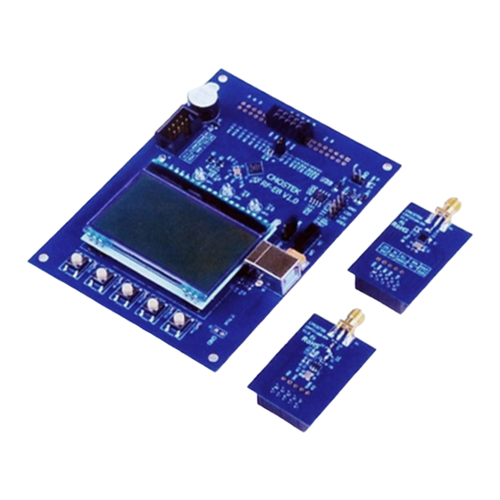
The Development Kits contain the components of two evaluation boards named RF-EB, a Tx evaluation module
named CMT2110A-EM, an Rx evaluation module named CMT2210A-EM, a USB Programmer and a PC
application named RFPDK (RF Products Development Kit). The package of the Development Kits is shown in
Figure 1.
Figure 1. CMT2110A/2210A One-Way RF Link Development Kits
Rev 1.0 | Page 1 / 23
www.cmostek.com
Copyright © By CMOSTEK
Advertisement
Table of Contents

Related Manuals for CMOSTEK CMT2110A


Summary of Contents for CMOSTEK CMT2110A
- Page 1 The CMT2110A is an ultra low-cost, highly flexible, high performance, single-chip OOK transmitter for various 240 to 480 MHz wireless applications. The CMT2210A is an ultra low-cost, highly flexible, high performance, single-chip OOK receiver for various 300 to 480 MHz wireless applications.
-
Page 2: Table Of Contents
7.4 Burn Log .............................. 18 7.5 Read Device ............................19 8. Frequently Asked Questions ........................20 9. Document Change List ..........................21 10. Appendix: CMT2110A-EM and CMT2210A-EM Schematics ..............22 11. Contact Information ..........................23 Rev 1.0 | Page 2 / 23 www.cmostek.com... - Page 3 Bill of Materials Radio Frequency Compact Disk Read Only Memory RF Products Development Kit CDROM RFPDK Evaluation Board Receiving, Receiver Evaluation Module(s) Transmission, Transmitter Error Symbol Rate On-Off Keying Universal Serial Bus Power Amplifier Rev 1.0 | Page 3 / 23 www.cmostek.com...
-
Page 4: Development Kits Contents
AN103 1. Development Kits Contents The Development Kits contain the following components: 2 x RF-EB V1.0 evaluation boards 2 x CMT2110A-EM V1.0 Tx module 2 x CMT2210A-EM V1.0 Rx module 1 x USB Programmer V1 ... - Page 5 CMT2110A, CMT2201A and other RF products. CMT2110A-EM The CMT2110A-EM is the Tx evaluation module. The user can use it to evaluate the CMT2110A performance and features. CMT2210A-EM The CMT2210A-EM is the Rx evaluation module.
-
Page 6: Application Schemes
This scheme allows the user to freely customize all product features and program them into the chips. Once the programming is done successfully, the evaluation module is ready to be integrated into the user’s own application systems. Moreover, the users can program chip configurations to their self-designed CMT2110A/2210A modules as long as the programming interface is reserved. - Page 7 Install the RFPDK to the computer. Refer to Section 7.1 for the detail procedure for the installation. Start Configuring CMT2110A/2210A on the RFPDK and the USB Programmer. Once the configuration is done, the user can use the evaluation modules in the actual RF system.
-
Page 8: Cmt2110A-Em
AN103 3. CMT2110A-EM The CMT2110A-EM is a Tx evaluation module with CMT2110A, the necessary external components and the matching network. The EM-Connector on the back side of the module allows the connection to the RF-EB or USB Programmer. The definitions of the EM-Connector pins are listed in Table 1. -
Page 9: Cmt2210A-Em
The evaluation module contained in this Development Kits is designed with the matching network at 433.92 MHz. For application with different frequencies, the matching network might need to be changed. See “Chapter 10 Appendix: CMT2110A-EM and CMT2210A-EM Schematics” for the CMT2210A-EM Schematic. Rev 1.0 | Page 9 / 23... -
Page 10: Rf-Eb
LED1 indicates that the RF-EB received 1 frame successfully when working with CMOSTEK Rx products. LED2 indicates that the RF-EB transmitted 1 frame out successfully when working with CMOSTEK Tx products. LED3 is reserved for future use. -
Page 11: Lcd Functional Icons
Power Switch – The power switch (SW1) allows the user to turn the RF-EB power on or off. It is recommended that the user shall power off the RF-EB before plugging in or out the CMT2110A-EM. USB Socket – A USB (type B) socket is used on the RF-EB. A USB cable is provided in the Development Kits for the user to connect the RF-EB to the PC. - Page 12 The symbol rate. The Rx and the Tx symbol rate must be identical. The number of bytes contained in the frame. The shorter the frame is, the lower PER is achieved. Rev 1.0 | Page 12 / 23 www.cmostek.com...
-
Page 13: Usb Programmer
AN103 6. USB Programmer The USB Programmer is the programming tool for the user to program the configuration into the CMOSTEK NextGenRF products with the RFPDK. The evaluation modules should be connected to the PC through the USB Programmer. There are 3 LEDs on the USB Programmer to indicate its working status. -
Page 14: Usb Socket
Development Kits for the user to connect the USB Programmer to the PC. The USB socket has two functions: Obtain power from the PC to supply the USB Programmer. Communicate to the RFPDK installed on the PC. Figure 9. USB Socket Rev 1.0 | Page 14 / 23 www.cmostek.com... -
Page 15: Rfpdk
RFPDK (RF Products Development Kit) is a member of the CMT2110A/2210A One-Way RF Link Development Kits supporting the development and manufacturing with CMOSTEK NextGenRF products. It is a PC application runs on Windows 2000, XP, 7 and 8. It works with the USB Programmer to configure the CMOSTEK NextGenRF products. - Page 16 AN103 Figure 12. Device Selection Panel Select the proper device, and then click “Next”, the Device Control Panel appears as below. Figure 13. Device Control Panel Rev 1.0 | Page 16 / 23 www.cmostek.com...
-
Page 17: Device Control Panel
Advanced Mode All settings of the selected device are available for the users to configure the device more flexibly. The details of each feature/setting are described in “AN102 CMT2110A Configuration Guideline” and “AN108 CMT2210A Configuration Guideline”. In both Basic and Advanced modes, default configurations can be loaded for direct use, or as a starting point to further customize the chip in the differentiating RF systems. -
Page 18: Status And Notice
The user can click the Export button to export the current configurations to an EEPROM image file suffixed by “.exp”. The file can be loaded by the manufacturing programmer in mass production phase to program the CMOSTEK NextGenRF products. ... -
Page 19: Read Device
The user can save the Burn Log to a text file by pressing the Save button. This text file is one of the necessary materials to send back to CMOSTEK when the user asks for any technical support. 7.5 Read Device When the device, the USB Programmer and the PC (RFPDK) are properly connected, the Read Device function can be used to read out and upload the EEPROM contents from the device to the PC. -
Page 20: Frequently Asked Questions
Q4. Can the RFDPK and the USB Programmer support all CMOSTEK RF products? A4. The current version of RFPDK and USB Programmer supports the existing RF products. In the future, CMOSTEK will update the RFPDK and USB Programmer firmware to support the new products. The user can visit www.cmostek.com... -
Page 21: Document Change List
AN103 9. Document Change List Table 9. Document Change List Rev. No Chapter Description of Changes Date Initial version 2014-06-14 Add Section 7.5 2014-06-30 Rev 1.0 | Page 21 / 23 www.cmostek.com... -
Page 22: Appendix: Cmt2110A-Em And Cmt2210A-Em Schematics
AN103 10. Appendix: CMT2110A-EM and CMT2210A-EM Schematics Figure 16. 433.92 MHz CMT2110A-EM Schematic Figure 17. 433.92 MHz CMT2210A-EM Schematic Rev 1.0 | Page 22 / 23 www.cmostek.com... -
Page 23: Contact Information
Copyright. CMOSTEK Microelectronics Co., Ltd. All rights are reserved. The information furnished by CMOSTEK is believed to be accurate and reliable. However, no responsibility is assumed for inaccuracies and specifications within this document are subject to change without notice. The material contained herein is the exclusive property of CMOSTEK and shall not be distributed, reproduced, or disclosed in whole or in part without prior written permission of CMOSTEK.
Need help?
Do you have a question about the CMT2110A and is the answer not in the manual?
Questions and answers