Table of Contents
Advertisement
Quick Links
Advertisement
Table of Contents

Summary of Contents for Acra 46SF
- Page 1 COMPLEX MACHINE MODEL 46SF INSTRUCTION MANUAL 46SF-080911-R3...
- Page 2 WARNING Some dust created by power sanding, sawing, grinding, drilling, and other construction activities contains chemicals known to the State of California to cause cancer, birth defects or other reprodrctive harm. Some examples of these chemical are: ‧Lead from lead-based paints. ‧Crystalline silica from bricks, cement and other masonry products.
-
Page 3: Table Of Contents
Table Of Contents Page No 1 Overall Aspect ………………………………………………………………… 2 2 Safety Rules For tools ………………………………………………………… 4 3 Specification …………………………………………………………………… 5 4 Features ……………………………………………………………………..… 6 5 Delivery & Installation …………………………………………………….. 6 6 Minimum Room Space For Machine Operation …………………………… 8 7 Use Of Main Machine Parts …………………………………………………. -
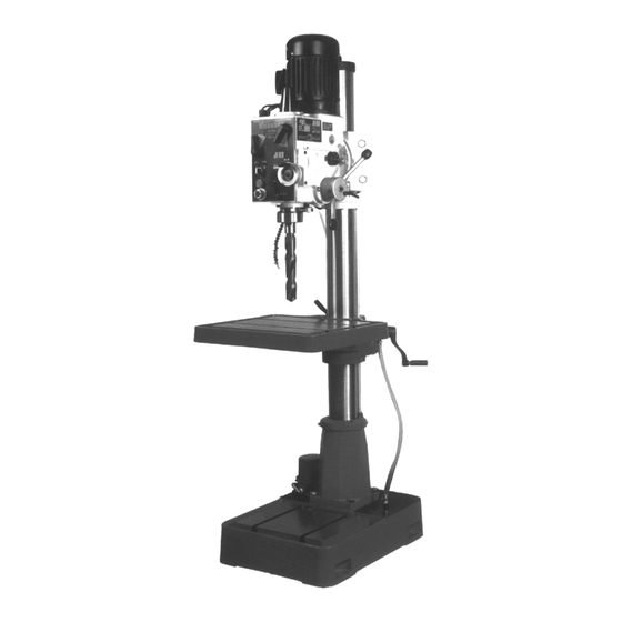
Page 4: Overall Aspect
Overall Aspect ARBOR BOLT COVER SPEED LEVER POWER DOWN FEED SPEED SELECTOR CONTROL SWITCH SPINDLE POWER DOWN FEED OPERATION HANDLE HANDLE ROD SCALE BASE GRIP TABLE LOCK HANDLE FINE FEED HAND WHEEL HANDLE COOLANT PUMP Fig. 1... -
Page 5: Safety Rules For Tools
WARNING: FAILURE TO FOLLOW THESE RULES MAY RESULT IN SERIOUS PERSONAL INJURY As with all machinery there are certain hazards involved with operation and use of the machine. Using the machine with respect and caution will considerably lessen the possibility of personal injury. - Page 6 4. USE RECOMMENDED ACCESSORIES. Consult the owner's manual for recommended accessories. The use of improper accessories may cause hazards. 5. AVOID ACCIDENTAL STARTING. Make sure switch is in “OFF” position before plugging in power cord. C. ADJUSTMENT : MAKE all adjustments with the power off. In order to obtain the machine. precision and correct ways of adjustment while assembling, the user should read the detailed instruction in this manual.
-
Page 7: Specification
1. SPECIFICATION MODEL 46SF Drilling capacity 42 mm (1 ") Face mill capacity 100 mm (4”) End mill capacity 25 mm Head swivel 360° Spindle taper MT-4 Spindle stroke 130 mm (5”) (PF=107mm) ø 75 mm (3”) Quill diameter 3ø 1... -
Page 8: Features
Tools selection & proper material range Tool type Tool material Work piece material Non-iron material steel iron End mill TUNGSTEN CARBIDE Cast iron non-iron material Face mill TUNGSTEN CARBIDE Non-iron material steel iron Light material Drilling Non-iron material steel iron Light material Tapping Non-iron material steel iron... - Page 9 Fig.B Installation: (1) BE SURE all locks of head-stock & column are tighten before operation. (2) ALWAYS Keep proper footing & balance while moving this 760lbs machine. And only use heavy duty fiber belt to lift the machine. (3) KEEP machine always out from sun, dust, wet, raining area. (4) POSITION &...
-
Page 10: Minimum Room Space For Machine Operation
4. MINIMUM ROOM SPACE FOR MACHINE OPERATION... -
Page 11: Use Of Main Machine Parts
5. USE OF MAIN MACHINE PARTS (See Fig. l) (1) Equipped with an electric switch for tapping operation clockwise or counterclockwise. (2) To adjust the quick or slow feeding by feed handle. (3) To operate the spindle handle wheel for micro feed. (4) To adjust the scale size according to working need. -
Page 12: Precaution For Operation
(12) Quill handle rod-can lock the spindle at desired position. (13) Chuck guard. (14) Switch. (15) Pump. (16) Adjusting the head height by loosening the head body fix bolt, and turning the head handle. 6. PRECAUTION FOR OPERATION Check all parts for proper condition before operation; if normal safety precautions are notice carefully, this machine can provide you withstanding of accurate service. -
Page 13: Adjusting Table Slack And Compensate For Wear
(4) Preparing for Drilling (see fig. 2)(Except addition power feed system). Turn of the knob make loose the taper body of worm gear and spring base. Then we decide spindle stroke setting the positive depth stop gauge for drilling blind hole or free state for pass hole. (5) Preparing for Milling (see fig. -
Page 14: Clamping / Table Base And Machine Base
8. CLAMPING, TABLE BASE, AND MACHINE BASE (see Fig. 3) (1) When milling longitudinal feed, it is advisable to lock the cross feed table travel to insure the accuracy of your work. To do this, tighten the small leaf screw located on the right side of the table base. -
Page 15: To Change Tools
10. TO CHANGE TOOLS (1) Removing Face Mill or Drill Chuck Arbor Loosen the arbor bolt (see fig. 4) at the top of the spindle shaft approximately 2 turns with a wrench. Rap the top of the arbor bolt with a mallet. After taper has been broken loose, holding chuck arbor on hand and turn detach the arbor bolt with the other hand. -
Page 16: Specification Of T Slot
(4) Turn the handle downwards, when the spindle leaving 1 limit switch (hear the sound), push the start button A, spindle will begin to run and prepare for tapping. (5) When reaching the bottom of your tapping depth, the spindle will reverse automatically. Release the handle, the spindle will return upwards to its original position, then stop running. -
Page 17: Maintaining
15. MAINTAINING That's easier to keep machine in good condition or best performance by means of maintaining it at any time than remedy it after it is out of order. (1) Daily Maintenance (by operator) (a) Fill the lubricant before starting machine everyday. (b) If the temperature of spindle caused over-heating or strange noise, stop machine immediately to cheek it for keeping accurate performance. -
Page 18: Changing The Gear Box Oil
(2) A light film of oil applied to the quill and column will reduce wear. prevent rust, and assure ease of operation. (3) Quill return spring should receive oil (SAE 20) once yearly. Remove cover plate and apply oil with squirt can or small brush. - Page 19 (4) Lack of power with main spindle revolving: (a) Motor has burned out - Change a new motor. (b) Fuse has burned out - Replace with new one. (5) Table travel has not balanced: (a) The gap of spindle taper too wide - Adjust bolt in proper. (b) Loosening of leaf bolt - Turn and fasten in place.
- Page 20 (c) Noisy spindle. – Lubricate spindle. (d) Noisy motor. – Check motor bearings or for loose motor fan. (12) Drill or Tool heats up or burns work: (a) Excessive speed. – Reduce speed. (b) Chips not clearing. – Use pecking operation to clear chips. (c) Dull tool.
-
Page 21: Circuit Diagram
CIRCUIT DIAGRAM... -
Page 22: Power Down Feed Operation
POWER DOWN FEED OPERATION: 1. Firs, check the proper feed speed for the object the cutter. 2. By adjusting the shift dial “A”(see Fig2), You can obtain the speed you need. The shift dial can be operated during the machine running or when the machine is stopped by turning it on clockwise or counter-clockwise. - Page 28 PARTS LIST MODEL NO. 46SF CODE NO PART NO DESCRIPTION SPECIFICATION NOTE 2450002SB Head Body Set 2401001-2 Main Shaft Cover 6101 MT3 M10xP1.5 Chuck Arbor Bolt 6101-1 MT3 M12xP1.75 Chuck Arbor Bolt 6101-2 MT3 W3/8"-16 Chuck Arbor Bolt 6101-3 MT3 W1/2"-12...
- Page 29 PARTS LIST MODEL NO. 46SF CODE NO PART NO DESCRIPTION SPECIFICATION NOTE ET0602 V-15FL2-1B CE(OPTION) Limit Switch W007 3/16" CE(OPTION) Washer S708 3/16"x3/8"L CE(OPTION) Cross Round Head Screw HS504 M3x15L CE(OPTION) Cross Round Head Screw E075732 CE(OPTION) Control Wire 61105S...
- Page 30 PARTS LIST MODEL NO. 46SF CODE NO PART NO DESCRIPTION SPECIFICATION NOTE 6158S Head Handle Set 6027-1S Clamp Handle Control Box S706 Cross Round Head Screw HP309S Miter Pin Set 62276 Nozzle Cock Support HS241 M8x16L Hex. Socket Head Screw 250250 1/4"...
- Page 31 PARTS LIST MODEL NO. 46SF CODE NO PART NO DESCRIPTION SPECIFICATION NOTE 2450003 Gear HS219 M5x12L Hex. Socket Head Screw HG003 ∮35x∮45x8t Oil Seal 2401008 Oil Seal Ring HB302 ∮35 Dust Cover CA6202ZZ 6202ZZ Bearing 2450005 Gear HS421 M6x6L Hex. Socker Headless Screw...
- Page 32 PARTS LIST MODEL NO. 46SF CODE NO PART NO DESCRIPTION SPECIFICATION NOTE 400S PDF40 Metric Power down feed Assembly (Option) 400S PDF40-1 Inch Power down feed Assembly (Option) 2450068S Gear Box Assembly 401-1 2450068 Gear Box 401-2 CA6003ZZ 6003ZZ Bearing...
- Page 33 PARTS LIST MODEL NO. 46SF CODE NO PART NO DESCRIPTION SPECIFICATION NOTE HS229 M6x12L Hex. Socket Head Screw HD101 7/8" Plug S416 5/16"x1-1/4"L Hex. Socket Head Screw 2450060 Scale HH001 ∮2x4L Rivet 2450059 Metric Speed Scale 2450059A Inch Speed Scale...
- Page 34 PARTS LIST MODEL NO. 46SF CODE NO PART NO DESCRIPTION SPECIFICATION NOTE 2450109 Rubber Plate 62201B Swivel Base 62279 ∮36 Filter 62270 Coolant Pump Cover HT001 M5x10L Round Head Screw 62277 PT3/8"x1/2L Pipe Connector 5/8" HD612 Binder MB13308C 1/8" Coolant Pump W202 1/4"...
- Page 35 PARTS LIST MODEL NO. 46SF CODE NO PART NO DESCRIPTION SPECIFICATION NOTE 62223 Lock Bolt 62243 Worm Gear 62259 Worm Shaft CA51103 51103 Bearing 5/16"x1"L S414 Hex. Socket Head Screw 62242 Head Raise Bracket 62244 Worm Shaft S604 1/4"x3/8"L Hex. Socker Headless Screw...
- Page 36 MANUFACTURER: ADDRESS: SERIAL No.: PLEASE WRITE DOWN THE SERIAL NO. ON THIS BLOCK FROM THE NAME PLATE AFTER YOU RECEIVE THIS MACHINE.
Need help?
Do you have a question about the 46SF and is the answer not in the manual?
Questions and answers