
Related Manuals for Buffalo filter ViroVac VV120


Summary of Contents for Buffalo filter ViroVac VV120
- Page 1 ViroVac ® Surgical Smoke Evacuator Service Manual BUFFALO FILTER www.buffalofilter.com +1 716.835.7000 (International) 800.343.2324 (United States) bf.techsupport@filtrationgroup.com...
- Page 2 www.buffalofilter.com +1 716.835.7000 (International) 800.343.2324 (United States) bf.techsupport@filtrationgroup.com...
- Page 3 Copyright and Non-Disclosure Buffalo Filter LLC asserts ownership and copyright, under all applicable law, over all designs, concepts, ideas, drawings, software, and any other intellectual property described or referred to in this manual (except where specifically identified otherwise). All or any part of this information may not be disclosed under any circumstances to any other company or other party without the express written consent of Buffalo Filter LLC.
-
Page 4: Table Of Contents
Table of Contents Introduction..................1-1 Purpose.....................1-1 Audience...................1-1 Precautions..................1-2 Warnings, Cautions, and Notices............1-3 Glossary....................1-5 Technical Support................1-6 Product Return...................1-6 Disposable Part Orders...............1-6 Replacement Part Orders..............1-6 System Overview..................2-1 General Description................2-1 Product Layout...................2-1 Major Assemblies................2-4 System Information................3-1 System Specifications................3-1 System References................3-3 System Operation.................4-1 Installation..................4-1 Filter Instructions................4-3 System Maintenance................5-1 General Maintenance.................5-1 Cleaning....................5-1... - Page 5 www.buffalofilter.com +1 716.835.7000 (International) 800.343.2324 (United States) bf.techsupport@filtrationgroup.com...
-
Page 6: Introduction
Surgical © Smoke Evacuator and its accessories. Audience This services manual is strictly for the use by a Buffalo Filter LLC trained technician. This service manual contains essential information to safely and effectively service the ViroVac Surgical Smoke © Evacuator. Instructions for the operation of the ViroVac Surgical Smoke Evacuator and related dangers, warnings, ©... -
Page 7: Precautions
Chapter 1 | Introduction Precautions NOTE: All Warnings, Cautions, and Notices should be read and understood before servicing the ViroVac Surgical Smoke Evacuator. © • Read this service manual thoroughly and be familiar with its contents prior to servicing the ViroVac Surgical ©... -
Page 8: Warnings, Cautions, And Notices
Chapter 1 | Introduction Precautions (continued) • The filter should be changed according to the filter life Indicator. The filter should not be used for more than the filter life specified. Failure to change the filter may result in decreased efficiency and possible internal contamination. - Page 9 Chapter 1 | Introduction Warnings, Cautions, and Notice (continued) Symbols DANGER – HIGH VOLTAGE CAUTION – ELECTRICAL SHOCK HAZARD. DO NOT REMOVE COVER. REFER SERVICING TO QUALIFIED SERVICE PERSONNEL. WARNING DANGER CAUTION – RISK OF EXPLOSION IF USED IN THE PRESENCE OF FLAMMABLE ANESTHETICS.
-
Page 10: Glossary
Chapter 1 | Introduction Glossary Name Description Ampere, unit of electric current. Automatic Activation Device Device used to remotely operate the ViroVac Surgical Smoke © Evacuator to control the suction on/standby modes in conjunction with ESU activation saving filter life (sold separately). CISPR International Special Committee on Radio Interference Electromagnetic Compatibility... -
Page 11: Technical Support
Chapter 1 | Introduction Technical Support Customer/Technical Services: +1 800.343.2324 (United States) +1 716.835.7000 (International) Buffalo Filter LLC 5900 Genesee Street Lancaster, New York 14086 USA www.buffalofilter.com Product Return Perform the following procedures if the ViroVac Surgical Smoke Evacuator is required to be returned to Buffalo ©... -
Page 12: System Overview
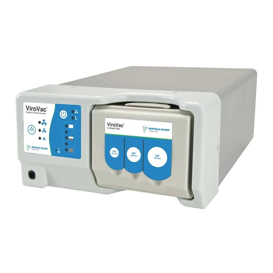
Chapter 2 | System Overview System Overview General Description The ViroVac Surgical Smoke Evacuator is designed to evacuate and filter surgical smoke and aerosols created © by the interface of surgical tools with tissue (examples: lasers, electrosurgery systems, and ultrasonic devices). There are three (3) system models of the ViroVac Surgical Smoke Evacuator: ©... -
Page 13: Front View
Chapter 2 | System Overview Product Layout (continued) Front View Motor On Indicator Suction On / Standby Button Motor Speed Control Button Low / Medium / High CONTROL PANEL Motor Speed Indicators Low / Medium / High Three-Port Filter Pneumatic with Footswitch Port Standby Indicator... - Page 14 Chapter 2 | System Overview Front and Rear Panel Instrument Descriptions NOTE: The Control Panel contains the following LED indicators: Motor On, Standby, Motor Speed, Filter Life, and Service. Read all instructions before servicing or operating the ViroVac © Surgical Smoke Evacuator or installing accessories. POWER ON/OFF To power on the ViroVac Surgical Smoke Evacuator, connect the supplied power cord to a grounded electrical...
-
Page 15: Major Assemblies
Bedienungsanleitung Manual del operador Manuel d'utilisation Manuale dell'operatore Brugervejledning Bedieningshandleiding Manual do operador Operatørhåndbok Användarhandbok Návod k obsluze BUFFALO FILTER 120 Power Cord 220 Power Cord Pneumatic Footswitch CD Electronic Manual Figure 2-3 Major Assemblies Fascia Assembly Figure 2-4 www.buffalofilter.com +1 716.835.7000 (International) - Page 16 Chapter 2 | System Overview Major Assemblies (continued) Body Assembly Figure 2-5 www.buffalofilter.com +1 716.835.7000 (International) 800.343.2324 (United States) bf.techsupport@filtrationgroup.com...
- Page 17 Chapter 2 | System Overview Major Assemblies (continued) Bottom Assembly Models VV120 and VV220 Model DKVV220 Figure 2-6 www.buffalofilter.com +1 716.835.7000 (International) 800.343.2324 (United States) bf.techsupport@filtrationgroup.com...
- Page 18 Chapter 2 | System Overview Major Assemblies (continued) Motor Block Assembly Models VV120 and VV220 Model DKVV220 Figure 2-7 www.buffalofilter.com +1 716.835.7000 (International) 800.343.2324 (United States) bf.techsupport@filtrationgroup.com...
- Page 19 Chapter 2 | System Overview www.buffalofilter.com +1 716.835.7000 (International) 800.343.2324 (United States) bf.techsupport@filtrationgroup.com...
-
Page 20: System Information
Chapter 3 | System Information System Information System Specifications Specifications pertain to the use of the ViroVac Surgical Smoke Evacuator, both domestically and © internationally: • Both the 100/120 V(ac), 50/60 Hz and the 220/240 V(ac), 50/60 Hz ViroVac Surgical Smoke Evacuator ©... - Page 21 © radio frequency energy and, if not installed and used in accordance with the guidelines set forth by Buffalo Filter LLC, may cause harmful interference to radio communications. Operation of the ViroVac © Surgical Smoke Evacuator in a residential area is likely to cause harmful interference in which case the user will be required to correct the interference at their expense.
-
Page 22: System References
Chapter 3 | System Information System References Performance References PERFORMANCE* Model Name / Description Models VV120 and VV220 Maximum Flow Setting (CFM-U.S.) Standard Hose I.D. 7/8 in. 25 CFM ** 3/8 in. 4.5 CFM 1/4 in. 2 CFM Standard Hose I.D. 22 mm 708 LPM ** 9.5 mm... - Page 23 Chapter 3 | System Information System References (continued) Electromagnetic Compatibility Information Table 1 Guidance and Manufacturer’s Declaration - Electromagnetic Emissions The ViroVac Surgical Smoke Evacuator is intended for use in the electromagnetic environment © specified below. The customer or user of the ViroVac Surgical Smoke Evacuator should ensure that it is used in such ©...
- Page 24 Chapter 3 | System Information System References (continued) Electromagnetic Compatibility (continued) Table 2 Guidance and Manufacturer’s Declaration - Electromagnetic Immunity The ViroVac Surgical Smoke Evacuator is intended for use in the electromagnetic environment specified © below. The customer or user of the ViroVac Surgical Smoke Evacuator should ensure that it is used in such ©...
- Page 25 Chapter 3 | System Information System References (continued) Electromagnetic Compatibility (continued) Table 3 Guidance and Manufacturer’s Declaration - Electromagnetic Emissions The ViroVac Surgical Smoke Evacuator is intended for use in the electromagnetic environment specified © below. The customer or user of the ViroVac Surgical Smoke Evacuator should ensure that it is used in ©...
- Page 26 Chapter 3 | System Information System References (continued) Electromagnetic Compatibility (continued) Table 4 Recommended Separation Distance Between Portable and Mobile RF Communications Equipment and the ViroVac Surgical Smoke Evacuator @ 3 Vrms © The ViroVac Surgical Smoke Evacuator is intended for use in the electromagnetic environment in ©...
- Page 27 Chapter 3 | System Information www.buffalofilter.com +1 716.835.7000 (International) 800.343.2324 (United States) bf.techsupport@filtrationgroup.com...
-
Page 28: System Operation
Chapter 4 | System Operation System Operation Installation Figure 4-1 1. Attach the power cord ( ) on page 4-2 to the power receptacle on the rear of the ViroVac Surgical © Figure 4-1 Smoke Evacuator and into a grounded electrical outlet ( ) on page 4-2. - Page 29 Chapter 4 | System Operation 120 Power Cord 220 Power Cord Pneumatic Footswitch Figure 4-1 Automatic Activation Device Port Equipotential Grounding Terminal Power Receptacle Figure 4-2 Motor On Indicator Suction On / Standby Button Motor Speed Control Button Low / Medium / High CONTROL PANEL Motor Speed Indicators...
-
Page 30: Filter Instructions
Figure 4-4 placed in the standby mode by pressing the Suction On/Standby Button ( Using any other filter or accessory not supplied by Buffalo Filter LLC may cause damage to the system and/or cause the ViroVac Surgical Smoke Evacuator to be inoperable. - Page 31 Chapter 4 | System Operation Filter Instructions (continued) Filter Removal NOTE: Before removing the filter, be sure that the ViroVac Surgical Smoke Evacuator is © Figure 4-4 placed in the Standby mode by pressing the Suction On/Standby Button ( ) on page 4-3.
-
Page 32: System Maintenance
Chapter 5 | System Maintenance System Maintenance General Maintenance It is recommended that periodic inspection and performance testing be completed by a qualified facility biomedical technician to ensure continued safe and effective operation of the ViroVac Surgical Smoke © Evacuator. Cleaning Disconnect the power from the ViroVac Surgical Smoke Evacuator before attempting to... - Page 33 Chapter 5 | System Maintenance Inspection (continued) Intake Vents Exhaust Vents Figure 5-1 Intake Vents Exhaust Vents Figure 5-2 www.buffalofilter.com +1 716.835.7000 (International) 800.343.2324 (United States) bf.techsupport@filtrationgroup.com...
-
Page 34: Troubleshooting
Chapter 6 | Troubleshooting Troubleshooting Troubleshooting Table PROBLEM POTENTIAL CAUSE CORRECTIVE ACTION ViroVac Filter is not seated Reinstall the filter, press firmly into place. © Surgical Smoke completely. Evacuator is on Filter is clogged. Replace the filter with a new filter from the but suction is manufacturer. - Page 35 Chapter 6 | Troubleshooting Troubleshooting Table (continued) PROBLEM POTENTIAL CAUSE CORRECTIVE ACTION Buttons not Fuse(s) are blown. Disconnect the power. Remove the fascia and the functioning on body. Check if one of the two fuses on the circuit control panel. board (PCB) are blown.
- Page 36 © NOTE: The fuses are CRITICAL COMPONENTS and must be replaced with exact parts Contact Buffalo Filter LLC for fuses. To check or replace fuse(s), see the fascia disassembly instructions and body disassembly instructions on pages 7-4 and 7-5 , respectively.
- Page 37 Chapter 6 | Troubleshooting Troubleshooting Table (continued) Fuse Locations Figure 6-1 www.buffalofilter.com +1 716.835.7000 (International) 800.343.2324 (United States) bf.techsupport@filtrationgroup.com...
-
Page 38: Repair
Chapter 7 | Repair Repair Precautionary Warnings NOTE: Proper care and maintenance of the ViroVac Surgical Smoke Evacuator is required © to ensure safe operation and service. Function and operation of the ViroVac Surgical Smoke © Evacuator shall be checked after each replacement session to protect patient and user. Always switch off and unplug the ViroVac Surgical Smoke Evacuator before ©... -
Page 39: Tools
Chapter 7 | Repair Precautionary Warnings (continued) To prevent possible injuries during disassembly or assembly, avoid sharp edges of metal parts or the printed circuit board to avoid injuring yourself. The ViroVac Surgical Smoke Evacuator contains electrostatic-sensitive components. © When repairing or servicing, work at a static-control workstation. Wear a grounding strap when handling electrostatic-sensitive components, except when working on an energized ViroVac Surgical Smoke Evacuator. -
Page 40: Tests
Chapter 7 | Repair Tests Electrical Insulation Test 1. Connect the ViroVac Surgical Smoke Evacuator with a hipot tester according to the tester’s © instructions. 2. Turn on the ViroVac Surgical Smoke Evacuator. © 3. Verify that the dielectric withstand is 1.5 kV at 1 second. Leakage Current Test 1. -
Page 41: Disassembly
Chapter 7 | Repair Disassembly Fascia 1. Remove the filter. Figure 7-1 2. Locate and remove the six (6) screws which secure the fascia assembly to the body assembly using a phillips Phillips Figure 7-1 screwdriver ( Screwdriver 3. Carefully remove the fascia from the body assembly. Taking care not to damage the connected wire harnesses. - Page 42 Chapter 7 | Repair Disassembly (continued) Keypad Figure 7-5 NOTE: If keypad is removed, it cannot be reused. 1. Remove the fascia assembly by following the Fascia Disassembly instructions on page 7-4. 2. Remove the KEYPAD VV by pulling it off of the face of the FASCIA VV.
- Page 43 Chapter 7 | Repair Disassembly (continued) Body 1. Remove the fascia assembly by following the Fascia Figure 7-6 Disassembly instructions on page 7-4. Phillips 2. Locate and remove the eight (8) screws which secure the Screwdriver HOUSING TOP VV to the housing bottom assembly using a Figure 7-6 phillips screwdriver ( 3.
- Page 44 Chapter 7 | Repair Disassembly (continued) Printed Circuit Board (PCB) 1. Remove the fascia assembly by following the Fascia Figure 7-8 Disassembly instructions on page 7-4. 2. Remove the HOUSING TOP VV by following the Body Motor Wires AC-LINE Disassembly instructions on page 7-6. AC-NEUT 3.
- Page 45 Chapter 7 | Repair Disassembly (continued) Motor Boot Assembly for Model DKVV220 1. Remove the fascia assembly by following the Fascia Figure 7-12 Disassembly instructions on page 7-4. 2. Remove HOUSING TOP VV by following the Body ELBOW 13_16 BARB X 1_2 Disassembly instructions on page 7-6.
- Page 46 Chapter 7 | Repair Disassembly (continued) Motor Boot Assembly for Model VV120 and VV220 1. Remove the Fascia Assembly by following the Fascia Figure 7-16 Disassembly instructions on page 7-4. 2. Remove the HOUSING TOP VV by following the Body Motor Wires Disassembly instructions on page 7-6.
- Page 47 Chapter 7 | Repair Disassembly (continued) Motor Boot Assembly for Model VV120 and VV220 (continued) 7. Separate the front and the back halves of the boot Figure 7-19 MOTOR BOOT assembly to expose the motor and media that can be FRONT VV Figure 7-19 replaced (...
-
Page 48: Reassembly
Chapter 7 | Repair Reassembly Motor Boot Assembly for Models VV120 and VV220 NOTE: When reinstalling the motor wires, make sure that Figure 7-22 the dimple on the Eterm is facing upwards towards the Motor grounding ring on the motor. Press downward towards the top of the motor and inward to properly install the two (2) grey motor wires. - Page 49 Chapter 7 | Repair Reassembly (continued) Motor Boot Assembly for Models VV120 and VV220 (continued) 9. Secure the filter basket to the housing bottom assembly Figure 7-25 with the four (4) nuts with washers using a 5/16 in. nut driver. Motor Wires NOTE: When tightening screws, do not exceed 10 inch- Ground Lug...
- Page 50 Chapter 7 | Repair Reassembly (continued) Motor Boot Assembly for Model DKVV220 1. Place the filter basket and the boot assembly into the Filter Basket Figure 7-27 Figure 7-27 housing bottom assembly ( NOTE: Make sure none of the wires get trapped under the boot assembly.
- Page 51 Chapter 7 | Repair Reassembly (continued) Motor Boot Assembly for Model DKVV220 (continued) 6. Install the elbow by screwing the elbow into the rear of the Figure 7-30 Figure 7-30 housing bottom assembly ( ELBOW 13_16 BARB X 1_2 NOTE: During the installation of the elbow, it is critical to BOOT Assembly not over tighten as it could lead to failure of adhesive.
- Page 52 Chapter 7 | Repair Reassembly (continued) Printed Circuit Board (PCB) 1. Mount the printed circuit board to the housing bottom Figure 7-32 assembly with the four (4) screws using a phillips screwdriver Figure 7-32 2. Connect the brown wire to the printed circuit board connector Figure 7-33 J1B (AC-LINE) ( 3.
- Page 53 Chapter 7 | Repair Reassembly (continued) Body 1. Place the HOUSING TOP VV on to the housing bottom Figure 7-36 Figure 7-36 assembly ( 2. Secure the HOUSING TOP VV to the housing bottom Phillips Screwdriver assembly with the eight (8) screws using a phillips Figure 7-36 screwdriver ( NOTE: When tightening screws, do not exceed 10 inch-...
- Page 54 Chapter 7 | Repair Reassembly (continued) Keypad NOTE: Be sure the surface of the fascia is clean before Figure 7-38 applying the new keypad. 1. Insert the keypad ribbon cable through the slot in the face of the FASCIA VV. 2.
- Page 55 Chapter 7 | Repair Reassembly (continued) Fascia 1. Connect the the ribbon cable tail of the KEYPAD VV to the Figure 7-39 Figure 7-39 printed circuit board connector J4 ( NOTE: Be sure the ribbon cable tail has no twists from the KEYPAD VV / J4 plastic to the printed circuit board.
-
Page 56: Parts List
Appendix A | Parts List Appendix A Parts List Housing Bottom www.buffalofilter.com +1 716.835.7000 (International) 800.343.2324 (United States) bf.techsupport@filtrationgroup.com... - Page 57 For VV120 only For VV220 and LBL SERIAL VV 220 DKVV220 NOTE: If labeling in callout 42 and 43 need to be replaced, the current labeling must be surrendered or returned to Buffalo Filter. www.buffalofilter.com +1 716.835.7000 (International) 800.343.2324 (United States) bf.techsupport@filtrationgroup.com...
- Page 58 Appendix A | Parts List Parts List (continued) Fascia Assembly CALLOUT DESCRIPTION REMARKS FASCIA VV PCB HARNESS 35 SCREW 3-24 5/8 PH PN PL SS — KEYPAD VV www.buffalofilter.com +1 716.835.7000 (International) 800.343.2324 (United States) bf.techsupport@filtrationgroup.com...
- Page 59 Appendix A | Parts List Parts List (continued) Body CALLOUT DESCRIPTION REMARKS NUT 6-32 W/WASHER SS — HOUSING TOP VV For VV120 and — HOUSING BOTTOM VV VV220 HOUSING BOTTOM VV — For DKVV220 only SEALED SCREW 6-32 5/16 PH FH SS www.buffalofilter.com +1 716.835.7000 (International) 800.343.2324 (United States)
- Page 60 Appendix A | Parts List Parts List (continued) Motor Boot Assembly for Model DKVV220 CALLOUT DESCRIPTION REMARKS NOTE: There are no field servicable parts. This is a sealed unit. Filter basket (FILTER BASKET VV) is removable and will be retained when motor boot assembly is returned. www.buffalofilter.com +1 716.835.7000 (International) 800.343.2324 (United States)
- Page 61 Appendix A | Parts List Parts List (continued) Motor Boot Assembly for Models VV120 and VV220 CALLOUT DESCRIPTION REMARKS MOTOR BOOT BACK VV MOTOR BOOT FRONT VV 220V MOTOR For VV220 only 120V MOTOR For VV120 only INSUL 1 VV INSUL 2 VV INSUL 3 VV FILTER BASKET VV...
- Page 62 ® defects in material or workmanship. Buffalo Filter LLC will repair or replace (at Buffalo Filter LLC option) the same without charge, provided that routine maintenance as specified in this manual has been performed using replacement parts approved by Buffalo Filter LLC. This warranty is void if the product is used in a manner or for purposes other than intended.
Need help?
Do you have a question about the ViroVac VV120 and is the answer not in the manual?
Questions and answers
Virovac is staying on even when cautery not in use. **** just keeps running
The Buffalo Filter ViroVac VV120 continues to run when the cautery is not in use because it does not automatically turn off. It will keep operating until it is manually turned off. Additionally, an Automatic Activation Device can be used to control the suction on/standby modes in conjunction with ESU activation, which helps in saving filter life.
This answer is automatically generated