TECO SG2 Series User Manual
Hide thumbs
Also See for SG2 Series:
- User manual (175 pages) ,
- Operation manual (189 pages) ,
- Manual (16 pages)

Related Manuals for TECO SG2 Series


Summary of Contents for TECO SG2 Series
-
Page 1: Table Of Contents
Table of Contents Chapter 1: Getting Started Examination before Installation Environmental Precautions SG2 Model Identification Quick Start Setup Chapter 2: Installation General Specifications Product Specifications Mounting Wiring Chapter 3: Program Tools PC Programming Software “SG2 Client” Memory Cartridge LCD Display and Keypad Chapter 4: Relay Ladder Logic Programming Common Memory Types Specialty Memory Types... - Page 2 NOR Logic XOR Logic SR Logic Block NOT Logic Block Pulse Logic Block Function Block Common Counter Function Block High Speed Counter Function Block Timer Function Block RTC Function Block Analog comparator Function Block Appendix: Application Illustration...
-
Page 3: Chapter 1: Getting Started
Chapter 1: Getting Started Chapter 1: Getting Started The SG2 tiny smart Relay is an electronic device. For safety reasons, please carefully read and follow the paragraphs with "WARNING" or "CAUTION" symbols. They are important safety precautions to be aware of while transporting, installing, operating, or examining the SG2 Controller. -
Page 4: Examination Before Installation
Chapter 1: Getting Started Precaution for Operation To insure safety with the application of the SG2 smart relay, complete functional and safety testing must be ducted. Only run the SG2 after all testing and confirming safe and proper operation is complete. Any potential faults in the application should be included in the testing. -
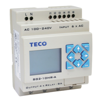
Page 5: Sg2 Model Identification
Chapter 1: Getting Started SG2 Model Identification SG2 - 20 Controller Type Input Power: D = 24V DC Powered I/O Count: 12D = 12V DC Powered 8 = 8 points (expansion modules) A = 100~240V AC Powered 10 = 10 I/O points 24A = 24V AC Powered 12 = 12 I/O points 20 = 20 I/O points... -
Page 6: Quick Start Setup
Quick Start Setup Quick Start Setup This section is a simple 5-steps guide to connecting, programming and operating your new SG2 smart relay. This is not intended to be the complete instructions for programming and installation of your system. Many steps refer to other sections in the manual for more detailed information. - Page 7 Quick Start Setup 3. Connect Programming Cable Remove the plastic connector cover from the SG2 using a flathead screwdriver as shown in the figure below. Insert the plastic connector end of the programming cable into the SG2 smart relay as shown in the figure below. Connect the opposite end of the cable to an RS232C serial port on the computer.
- Page 8 Quick Start Setup Select the correct Com Port number where the programming cable is connected to the computer then press the “Link” button. The SG2 Client will then begin to detect the connected smart relay to complete its connection as shown below. 5.
- Page 9 Quick Start Setup Use the “A” key on your keyboard (or the “A” icon from the ladder toolbar) to draw the horizontal circuit line from the M contact to the right most cell, as shown below. Select the “Q” coil icon from the ladder toolbar and drop it on the right most cells. Select Q1 from the dialog and press OK as shown below.
- Page 10 Quick Start Setup Test the simple program. From the Operation menu, select the Write function and write the program to the connected smart relay as shown below. Select the RUN icon from the toolbar, and select “No” when the pop-up message asks “Do you want to read program from module?”, as shown below.
- Page 11 Quick Start Setup From the Input Status dialog, click on M1 to activate the contact M1 which will turn ON the Output Q1, as shown below. The highlighted circuit will show active and the first Output (Q1) on the connected smart relay will be ON. See Chapter 3: Programming Tools for more detailed software information.
-
Page 12: Chapter 2: Installation
Chapter 2 Installation Chapter 2: Installation General Specifications SG2 is a miniature smart Relay with a maximum of 44 I/O points and can be programmed in Relay Ladder Logic or FBD (Function Block Diagram) program. The SG2 can expand to its maximum I/O count by adding 3 groups of 4-input and 4-output modules. - Page 13 Chapter 2 Installation Discrete Inputs 3.2mA @24VDC @12VDC Current consumption 1.3mA @100-240VAC 3.3mA @24VAC 24VDC: < 5VDC; 12VDC: < 2.5VDC Input Signal ”OFF” Threshold 100-240VAC : < 40VAC 24VAC: <6VAC 24VDC: > 15VDC; 12VDC: > 7.5VDC Input Signal ”ON” Threshold 100-240VAC : >...
-
Page 14: Product Specifications
Chapter 2 Installation Product Specifications Display & Part # Input Power Inputs Outputs RS-485 Communications Max I/O Keypad □, Z1-Z4 SG2-12HR-D 6 DC, 2 Analog 4 Relay 36 + 4 □, Z1-Z4 SG2-12HT-D 6 DC, 2 Analog 4 Trans. 36 + 4 □, Z1-Z4 SG2-20HR-D 8 DC, 4 Analog... -
Page 15: Mounting
Chapter 2 Installation Mounting DIN-rail Mounting The SG2 smart relay should always be mounted vertically. Press the slots on the back of the SG2 and expansion module plug CONNECTOR onto the rail until the plastic clamps hold the rails in place. - Page 16 Chapter 2 Installation It is recommended to apply a DIN-rail end clamp to hold the SG2 in place. X3 X4 Input 4 × AC AC 100~240V DC 24V Input 8 x DC(A1,A2 0~10V) SG2-8ER-A SG2-12HR-D Output 4 x Relay / 8A Output 4 x Relay / 8A Direct Mounting Use M4 screws to direct mount the SG2 as shown.
-
Page 17: Wiring
Chapter 2 Installation Wiring WARNING: The I/O signal cables should not be routed parallel to the power cable, or in the same cable trays to avoid the signal interference. To avoid a short circuit on the load side, it is recommended to connect a fuse between each output terminals and loads. - Page 18 Chapter 2 Installation I1 V1 C1 PE DC 24v DC 24v SG2-4AI SG2-4AI Input 4 x (0..10V/0..20mA) Input 4 x (0..10V/0..20mA) I2 V2 C2 I3 V3 V4 C4 Input 100~240V /24V AC I5 I6 I5 I6 AC ..V Input ..AC ..V INPUT ..
- Page 19 Chapter 2 Installation Output (Transistor) OUTPUT 4 x TR / 0.5A OUTPUT 8 x TR / 0.5A Data Link OR Remote I/O Link A1 A2 A1 A2 RS485 RS485 RS485 The power supply and the I/O supply should share the same power source. Only short circuit the first and the last module.
-
Page 20: Chapter 3: Program Tools
Chapter 3 Program Tools Chapter 3: Program Tools PC Programming Software “SG2 Client” The SG2 Client programming software provides two edit modes, Ladder Logic and Function Block Diagram (FBD). The SG2 Client software includes the following features: 1. Easy and convenient program creation and editing. 2. - Page 21 Chapter 3 Program Tools Start Screen the SG2 Client softw are and the following Start screen will be displayed. From this screen, can perform the follow ing functions w Ladder Program Select File -->New -->New LAD enter development nvironment for a new Ladder program.
- Page 22 Chapter 3 Program Tools Menus, Icons and Status Displays The Ladder programming environment includes the following Menus, Icons and Status Displays 1. Menu bar – Five menu selections for program development and retrieval, editing, communication to connected controllers, configuration of special functions and viewing preference selections. 2.
- Page 23 Chapter 3 Program Tools Programming The SG2 Client software can be programmed by either drag-and-drop of instructions or by using keyboard entry commands. Below is an example of some common methods of enter programming instructions. Click-&- release Click- &-drag The “A” and “L” keys or icons are used to complete parallel and serial circuits. The rightmost column is for output coils.
- Page 24 Chapter 3 Program Tools ulation Mode SG2 Client software includes a built-in simulator to test and debug programs easily without the need f or downloading to a controller. To activate simulation mode, simply press the red RUN icon. The program below is shown in simulation mode, identifying the significant available features. stablish Communication he following is the simple procedure for establishing communication between the connect C and the SG2 smart relay.
- Page 25 Chapter 3 Program Tools b. Select the correct Com Port number where the programming cable is connected to the computer then press the “Link” button. c. The SG2 Client software will then begin to detect the connected smart relay to complete it’s connection as shown below.
- Page 26 Chapter 3 Program Tools Online Monitoring/Editing The SG 2 Client software allows for online monitoring of the currently running program during runtim e. Additional online functions include, I/O forcing, and Mode chan ges (Run/Stop/Quit). Note: The SG2 Client software does not support runtime logic editing changes. All logic edits to contacts, coils, timers/counters, and circuit connecting lines must be written to the connected smart relay while in Stop mode.
- Page 27 Chapter 3 Program Tools Program Documentation he SG2 Client software includes the ability to document a program using Symbols and Line omments. Symbols are used to label each I/O address up to a length of 12 characters. Line omments are used to document sections of a program. Each Line Comment can have up to 4 es with each line containing up to 50 characters in length.
-
Page 28: Memory Cartridge
Chapter 3 Program Tools ory Cartridge (sold separ ately) The optional PM05 memory cartridge is used to easily transfer programs from one smart relay to another. The PM05 memory car ridge plugs into the sa me connector as the programming cable (see pr cedure below). -
Page 29: Lcd Display And Keypad
Chapter 3 Program Tools LCD Displa y and Keypad Keypad st SG2 CPU units include the built-in LCD Displa y and Keypad. The keypad and display are most often ed for changing timer/cou nter set points, controller mode changes (Run/Stop), uploading/dow nloading to the PM05 mem ory cartridge, and updating the RTC (Real Time... - Page 30 Chapter 3 Program Tools ( 2 ) The Main Menu as SG2 und er ‘ U R N’ Mode. > LADDER FUN.BLOCK STOP WRITE RTC SET WRITE PASSWORD LANGUAGE Press the Button ↑ ↓ Move the Cursor to select Main Menu Confirm the selected Function Skip to Initial Screen ※SG2 can be modified, edited, cleared and read user program only when it is under STOP Mode.
- Page 31 Chapter 3 Program Tools peration Sample: 6 7 8 Column Line 1 > L A F U N . B L O C K R U N C L E A R P R O G . Procedure 1: 6 7 8 Colum Press ‘OK’...
- Page 32 Chapter 3 Program Tools Automatically Link Procedure 7 : 6 7 8 Colum Line 1 q 4 ⎯ Press ‘OK’ (Move the cursor to character in column 3) Automatically Link Procedure 7 : 6 7 8 Column Line 1 q 4 ⎯ Press ‘→’...
- Page 33 Chapter 3 Program Tools Change Wire ‘ -’ to ‘ I ’ Procedure 13 : 6 7 8 Column ┬ M 1 ⎯ I 3 ⎯ ( Q 1 Press ‘SEL’ Line ┴ (A vertical line emerges) Procedure 14 : 6 7 8 Column ⎯...
- Page 34 Chapter 3 Program Tools Procedure 19 : 6 7 8 Column 1 q 4 ┬ M 1 ⎯ I 3 ⎯ ( Line Press ‘↑’ for 7 times ┴ r 3 ⎯ ⎯ ⎯ ⎯ ( C 7 (Press ‘SEL’ + ‘↑ ↓’ The digital 1 the cursor locating will change to 7) Auto Enter Function...
- Page 35 Chapter 3 Program Tools Procedure : Column ⎯ ⎯ Press ‘SEL+DEL’ (Simultaneously) Line ┬ M 1 ( Q 1 ┴ r 3 ⎯ ⎯ ⎯ ⎯ 3 C L E A R 0 0 2 (‘ESC’ Cancel , ‘OK’ Execute) 4 E S C Insert a whole line.
- Page 36 Chapter 3 Program Tools Line 1 ┌ 1 ┐ Never press ‘→’ to move to the digital position. 1 ┤ │ (If T2 is required to be changed, │ 0 0 . 0 0 ├ ┴ ┘ Press ‘↑’/‘↓’ and ‘SEL’ to execute.) Step 2: modify present target value preset the action relay...
- Page 37 Chapter 3 Program Tools Step2-3A: column Press ‘SEL’ line 1 ┌ 1 ┐ 1 ┤ │ │ V ├ T 1 ┴ ┘ Repeat the step 2-3A, the following screen will be shown in turn: Step2-3 column Press ‘SEL’ line 1 ┌...
- Page 38 Chapter 3 Program Tools Procedure 2-9: 6 7 8 Column Line 1 ┌ 1 ┐ Press ‘↑’ 2 ┤ │ (Press ‘SEL’ + ‘ ↑, ↓’ │ ├ T 1 to change1’ to ‘ 2’) ┴ ┘ Procedure 2-10: 6 7 8 Column Press ‘OK’...
- Page 39 Chapter 3 Program Tools Procedure 2-16A: Column Press ‘SEL’ Line ┌ ┐ 2 ┤ │ (Begin to modify ) │ 3 3 3 . 3 ├ T 1 4 I 1 ┴ ┘ Repeat the step 2-16A, the following scr een will be shown in turn: Procedure 2-16B: 6 7 8...
- Page 40 Chapter 3 Program Tools rocedure 2-22: Column Line ┌ ┐ Press ‘↑’ 2 ┤ │ (Move the cursor to position ‘2’ to │ 3 3 3 . 3 ├ T 1 repeat the 2-8) 4 M 4 ┴ ┘ The detail operation of modify the analog comparator x, Ay: ep 2-22A: column line 1...
- Page 41 Chapter 3 Program Tools Procedure 1: 6 7 8 Column Line 1 ┌ 2 ┐ Press ‘SEL+↑’ (Simultaneously) 1 ┤ │ │ 0 1 0 . 0 ├ T 2 4 I 2 ┴ ┘ Last Function Block 6 7 8 Column Line 1 ┌...
- Page 42 Chapter 3 Program Tools ◎ RUN or STOP (1) RUN Mode (2) ST P Mode UN PROG. STOP PROG. >YES >YES ↑ ↓ M e the cursor Execute the instruction, then back to main menu Back to main menu u Item ◎Other (1) CLEAR PROGRAM (Clear RAM, EEPROM and Password at the same tim CLEAR PROG.
- Page 43 Chapter 3 Program Tools Now Pres : ↑ ↓ ← → Move the ur c sor Begin to edit. Press ‘SEL’ Move the cursor for ‘ID SET item’ ‘← → ’ Press ‘SEL ’ 1. ID SET= ~99 ; I/O NUMBER=0~3 ↓’...
- Page 44 Chapter 3 Program Tools (7) PASSWORD (setting password) PASSWORD ╳ PASSWORD 0 0 0 0 * * * * Now Press 1. Begin to input numeral 2. When the password is ON, it will not display 0000, but ****. Press ‘SEL’ Move the cursor + ‘←...
- Page 45 Chapter 3 Program Tools (8)INITIAL (select Ladder Logic and Function Block Diagram (FBD)) INITIAL > LADDER √ Now Press: Press ‘↑ ↓’ Vertically move the Cursor Select the language the cursor located Back to Main Menu The origin program will be cleared as the change of edition method.
-
Page 46: Chapter 4: Relay Ladder Logic Programming
Chapter 4 Relay Ladder Logic Programming Chapter 4: Relay Ladder Logic Programming Common Memory Types General output SET output RESET output PULSE output N.O. Contact N.C. Contact Number Symbol (N.O. / N.C.) Input contact 12 (I1-IC / i1-iC) Keypad input 4(Z1-Z4 / z1-z4) Output coil 8 (Q1-Q8 / q1-q8) - Page 47 Chapter 4 Relay Ladder Logic Programming Timers and Timer Status Bits (T Memory Type) Timer status bits provide the relationship between the current value and the preset value of a selected timer. The timer status bit will be on when the current value is equal or greater than the preset value of a selected timer.
-
Page 48: Specialty Memory Types
Chapter 4 Relay Ladder Logic Programming Specialty Memory Types General output SET output RESET output PULSE output N.O. Contact N.C. Contact Number Symbol (N.O. / N.C.) Used in function block Expansion input coil 12 (X1-XC /x1-xC) Expansion output coil 12 (Y1-YC / y1-yC) Differential (one shot) D (Positive) d (Negative) -
Page 49: Output Instructions
Chapter 4 Relay Ladder Logic Programming Output Instructions Set Output Instruction (Latch) ( A set output instruction, or Latch, turns ON an output coil (Q) or an auxiliary contact (M) when the preceding input contact transitions from OFF to ON. Once the output is ON or set, it will remain ON until it is reset using the Reset output instruction. - Page 50 Chapter 4 Relay Ladder Logic Programming Pulse Output Instruction (Flip-Flop) ( A pulse output instruction, or Flip-Flop, turns ON a coil (Q) or an auxiliary contact (M) when the preceding input contact transitions from OFF to ON. Once the output is ON, it will remain ON until the preceding input contact transitions from OFF to ON a second time.
-
Page 51: Counter Instructions
Chapter 4 Relay Ladder Logic Programming Counter Instructions The SG2 includes a total 15 separate counters that can be used throughout a program. Each counter has a choice of 8 operation modes, 6 for general purpose counting and 2 for high speed counting. Additionally, each counter has 6 parameters for proper configuration. - Page 52 Chapter 4 Relay Ladder Logic Programming Counter Mode 1 (Fixed Count, Non-Retentive) Mode 1 Counter will count up to a fixed preset value and stop counting when the current count is equal to the preset value. Additionally, the current count value is non-retentive and will reset to zero on a loss of power to the smart relay.
- Page 53 Chapter 4 Relay Ladder Logic Programming Counter Mode 2 (Continuous Count, Non-Retentive) Mode 2 Counter will count up to a fixed preset value and continue counting after the preset value. Additionally, the current count value is non-retentive and will reset to zero on a loss of power to the smart relay. In the example below, the counter will continue counting after its preset value of 20.
- Page 54 Chapter 4 Relay Ladder Logic Programming Counter Mode 3 (Fixed Count, Retentive) Mode 3 Counter operation is similar to Mode 1 except its current count value is retentive. Mode 3 Counter will count up to a fixed preset value and stop counting at that value. Additionally, the current count value is retentive and will keep its current count after a loss of power to the smart relay.
- Page 55 Chapter 4 Relay Ladder Logic Programming Counter Mode 5 (Continuous Count, Up-Down Counter, Non-Retentive) Mode 5 Counter operation is similar to Mode 2 where its current count value is continuous and non- retentive, except its C1 status bit will only be ON when the counter counts up to its preset, or down to its preset from a count higher than its preset.
- Page 56 Chapter 4 Relay Ladder Logic Programming Counter Mode 6 (Continuous Count, Up-Down Counter, Retentive) Mode 6 Counter operation is similar to Mode 4 where its current count value is continuous and retentive, except its C1 status bit will only be ON when the counter counts up to its preset or down to its preset from a count higher than its preset.
-
Page 57: High Speed Counters (Dc Version Only)
Chapter 4 Relay Ladder Logic Programming High Speed Counters (DC Version Only) The DC powered version smart relays include two 1 KHz high speed inputs on terminal I1 and I2. These can be used as general purpose DC inputs or can be wired to a high speed input device (encoder, etc.) when configured for high speed counting. - Page 58 Chapter 4 Relay Ladder Logic Programming High Speed Counter Mode 8 (DC powered versions only) The Mode 8 High Speed Counter can use either input terminals I1 or I2 for forward up-counting to 1 KHz maximum at 24VDC high speed input signal. The selected Counter Coil (C1-CF) will turn ON when the pulse count reaches the target “Preset ON”...
-
Page 59: Timer Instructions
Chapter 4 Relay Ladder Logic Programming Timer Instructions The SG2 includes a total of 15 separate timers that can be used throughout a program. Each timer has a choice of 8 operation modes, 7 for general purpose timing and 1 (mode 7) for a pulse timer. Additionally, each timer has 6 parameters for proper configuration. - Page 60 Chapter 4 Relay Ladder Logic Programming Timer Mode 1 (ON-Delay) Mode 1 Timer (ON-Delay) will time up to a fixed preset value and stop timing when the current time is equal to the preset value. Additionally, the current time value is non-retentive and will reset to zero on a loss of power to the smart relay.
- Page 61 Chapter 4 Relay Ladder Logic Programming Timer Mode 2 (ON-Delay with Reset) Mode 2 Timer is an ON-Delay with reset that will time up to a fixed preset value and stop timing when the current time is equal to the preset value. Additionally, the current time value is non-retentive and will reset to zero on a loss of power to the smart relay.
- Page 62 Chapter 4 Relay Ladder Logic Programming Timer Mode 3 (OFF-Delay) Mode 3 Timer is an OFF-Delay with reset that will time up to a fixed preset value and stop timing when the current time is equal to the preset value. Additionally, the current time value is non-retentive and will reset to zero on a loss of power to the smart relay.
- Page 63 Chapter 4 Relay Ladder Logic Programming Timer Mode 4 (OFF-Delay) Mode 4 Timer is an OFF-Delay with reset that will time up to a fixed preset value and stop timing when the current time is equal to the preset value. Additionally, the current time value is non-retentive and will reset to zero on a loss of power to the smart relay.
- Page 64 Chapter 4 Relay Ladder Logic Programming Timer Mode 5 (FLASH without Reset) Mode 5 Timer is a Flash timer without reset that will time up to a fixed preset value then change the state of its status bit when the current time is equal to the preset value. Additionally, the current time value is non-retentive and will reset to zero on a loss of power to the smart relay.
- Page 65 Chapter 4 Relay Ladder Logic Programming Timer Mode 6 (FLASH with Reset) Mode 6 Timer is a Flash timer with reset that will time up to a fixed preset value then change the state of its status bit when the current time is equal to the preset value. Additionally, the current time value is non- retentive and will reset to zero on a loss of power to the smart relay.
- Page 66 Chapter 4 Relay Ladder Logic Programming Timer Mode 7 (FLASH Cascade without Reset) Mode 7 Timer is a Flash timer without reset that uses two timers in a cascade configuration. The cascade configuration connects the timer status bit of first timer to enable the second timer. The second timer will time up to its preset value then flash and its timer status bit will enable the first timer.
-
Page 67: Real Time Clock (Rtc) Instructions
Chapter 4 Relay Ladder Logic Programming Real Time Clock (RTC) Instructions The SG2 smart relay includes a total of 15 separate RTC instructions that can be used throughout a program. Each RTC instruction has a choice of 5 operation modes, and has 10 parameters for proper configuration. - Page 68 Chapter 4 Relay Ladder Logic Programming RTC Mode 1 (Daily ) The Daily Mode 1 allows the Rx coil to activate based on a fixed time across a defined set of days per week. The configuration dialog below allows for selection of the number of days per week (i.e. Mon-Fri) and the Day and Time for the Rx coil to activate ON, and Day and Time for the Rx coil to deactivate OFF.
- Page 69 Chapter 4 Relay Ladder Logic Programming RTC Mode 2 (Interval weekly) The Interval Time Mode 2 allows the Rx coil to activate based on time and day per week. The configuration dialog below allows for selection of Day and Time for the Rx coil to activate ON, and Day and Time for the Rx coil to deactivate OFF.
- Page 70 Chapter 4 Relay Ladder Logic Programming RTC Mode 3 (Year-Month-Day) The Year-Month-Day Mode 3 allows the Rx coil to activate based on Year, Month, and Date. The configuration dialog below allows for selection of Year and Date for the Rx coil to activate ON, and Year and Date for the Rx coil to deactivate OFF.
- Page 71 Chapter 4 Relay Ladder Logic Programming RTC Mode 4 ( 30-second adjustment) The 30-second adjustment Mode 4 allows the Rx coil to activate based on week, hour, minute and second. The configuration dialog below allows for selection of week, hour, minute and second for the Rx coil to activate ON, and 30-second adjustment then Rx OFF.
-
Page 72: Comparator Instructions
Chapter 4 Relay Ladder Logic Programming Comparator Instructions The SG2 smart relay includes a total of 15 separate comparator instructions that can be used throughout a program. Each comparator has a choice of 6 operation modes. Additionally, each comparator has 7 parameters for proper configuration. - Page 73 Chapter 4 Relay Ladder Logic Programming Analog comparator Mode 1~5 When the relay of analog comparator is ON, there are 5 operation modes described below: (1) Analog Comparator mode 1 ( AY - ⑥ ≤ AX≤ AY +⑥, ⑦ ON) (2) Analog Comparator mode 2 (AX ≤...
-
Page 74: Hmi Display Instructions
Chapter 4 Relay Ladder Logic Programming Example 2: Timer/Counter Preset Value Compare The Comparator instruction can be used to compare Timer, Counter, and RTC values to a constant value or to each other. In this example below, Mode 5 is the selected function that compares the value of Counter (C1) to a constant value (N) of 15 counts (the decimal point is ignored). - Page 75 Chapter 4 Relay Ladder Logic Programming Allows the HMI message to include coil number and selected value (i.e. T1=003 sec). Provides access to the Analog Display Set dialog for gain and offset parameters shown below. The Analog Display Set dialog allows the user to specify a scaling factor (Gain) and an offset for each analog input value.
-
Page 76: Pwm Output Instruction (Dc Transistor Output Models Only)
Chapter 4 Relay Ladder Logic Programming PWM Output Instruction (DC Transistor Output Models Only) The transistor output model smart relay includes the capability to provide a PWM (Pulse Width Modulation) output on terminal Q1. The PWM instruction is able to output up to an 8-stage PWM waveform. Symbol Description Enable Output PWM... -
Page 77: Data Link/Remote I/O Instruction (Sg2-20Vxx Models Only)
Chapter 4 Relay Ladder Logic Programming Data Link/Remote I/O Instruction (SG2-20Vxx Models Only) The SG2-20Vxxx transistor output models include the capability to link additional SG2-20Vxx units via the RS-485 connection terminals. Up to 8 additional SG2 units can be configured as independent Slave nodes, each running their own logic program and their I/O linked to one Master smart relay. - Page 78 Chapter 4 Relay Ladder Logic Programming Example 1: Data Link Mode 1 ① ② ③ = 1, = 5, set as the initiate of I3, the state of actual sending terminal I3~I7 is sent to memory list; the controller ID = 3, the state of corresponding memory list position W25~W32, and relationship of sending terminal is as below: Example 2: Data Link Receive mode 2 ①...
-
Page 79: Chapter 5: Function Block Diagram Programming
Chapter 5 FBD Programming Chapter 5: Function Block Diagram Programming FBD Instructions Note: FBD program can only be edited and modified in SG2 Client software and write to SG2 controlled equipments via communication cable. Via controlled equipment, FBD program is available for querying or the parameter of the function block of the program for modifying. -
Page 80: Pwm Function Block
Chapter 5 FBD Programming PWM Function Block The PWM output terminal ‘Q1’ can output 8 PWM waveforms. (Only provided for transistor output version) -
Page 81: Shift Function Block
Chapter 5 FBD Programming SHIFT Function Block Symbol Description SHIFT code (Total 1 group) Set output type (Q, Y) Set output shift number (1-8) -
Page 82: Logic Block Instructions
Chapter 5 FBD Programming Logic Block Instructions AND Logic Diagram FBD: LADDER: → I01 And I02 And I03 Note:The input terminal is NOP which is equivalent to ‘Hi’ AND (EDGE) Logic Diagram FBD: LADDER: → I01 And I02 And I03 And D Note:The input terminal is NOP which is equivalent to ‘Hi’... -
Page 83: Nand Logic Block
Chapter 5 FBD Programming NAND Logic Diagram FBD: LADDER: → Not(I01 And I02 And I03) Note:The input terminal is NOP which is equivalent to ‘Hi’ NAND (EDGE) Logic Diagram FBD: LADDER: → Not(I01 And I02 And I03) And d Note:The input terminal is NOP which is equivalent to ‘Lo’ OR Logic Diagram FBD: LADDER:... -
Page 84: Xor Logic
Chapter 5 FBD Programming XOR Logic Diagram FBD: LADDER: → I01 Xor I02 Note:The input terminal is NOP which is equivalent to ‘Lo’ SR Logic Diagram FBD: LADDER: → Logic I01 I02 Bxx Table holding Note:The input terminal is NOP which is equivalent to ‘Lo’ NOT Logic Diagram FBD: LADDER:... -
Page 85: Function Block
Chapter 5 FBD Programming Function Block The function blocks are classified into 4 sorts: Time, Counter, RTC Comparator ‘R’ and Analog Comparator ‘G’. The Operation Fundamental is similar to LADDER Function Block’s. Common Counter Function Block (1) Counter Mode 1 →... -
Page 86: High Speed Counter Function Block
Chapter 5 FBD Programming (4) Counter Mode 4 → Counting Input → Up/Down Counting → Reset → Counting Parameter (5) Counter Mode 5 → Counting Input → Up/Down Counting → Reset → Counting Parameter Note:The “C”means that will keep the current value in 0 during the Reset pin be enable. (6) Counter Mode 6 →... -
Page 87: Timer Function Block
Chapter 5 FBD Programming Timer Function Block imer mode 0 (Internal coil Mode) → Enable Input (2) Timer mode 1 (ON-Delay A Mode) → Enable Input → Timing Parameter (3) Timer mode 2 (ON-Delay B Mode) → Enable Input → Reset →... -
Page 88: Rtc Function Block
Chapter 5 FBD Programming (6) Timer mode 5(FLASH A Mode) → Enable Input → Timing Parameter (7) Timer mode 6(FLASH B Mode) → Enable Input → Reset → Timing Parameter (8) Timer mode 7(FLASH C Mode) → Enable Input → Timing Parameter RTC Comparator Function Block (1) RTC Mode 0(Internal Coil) -
Page 89: Analog Comparator Function Block
Chapter 5 FBD Programming (3) RTC Mode 2 (Continuous) → Enable Input → RTC Parameter (4) RTC Mode 3 (Year Month Day) → Enable Input → RTC Parameter (5) RTC Mode 4(30-second adjustment) → Enable Input → RTC Parameter Analog Comparator Function Block (1) Analog Comparison Mode 0 (Internal coil) →... - Page 90 Chapter 5 FBD Programming (3) Analog Comparison Mode 2 → Enable Input → Analog Input → Analog Input → Reference (4) Analog Comparison Mode 3 → Enable Input → Analog Input → Analog Input → Reference (5) Analog Comparison Mode 4 →...
-
Page 91: Appendix Application Illustration
Appendix Application Illustration Appendix Application Illustration 1. Lighting Control for Staircase 1.1 Requirement for Staircase Lighting When someone goes up-stair or down-stair, the lighting system shall be energized to provide sufficient luminance. After the walker passes the staircase, lighting system shall be turned off in five minutes automatically or manually. - Page 92 Appendix Application Illustration 1.3 Apply SG2 in Lighting System Devices Applied Lamp H1 I1(No terminal) Switch B1 I2(No terminal) Infrared sensor for climbing Wiring Diagram for Lighting System Illustrated program using SG2 in lighting system Ladder & FUNCTION:...
- Page 93 Appendix Application Illustration FBD: 2 Auto Door Control The auto doors are very popularly installed at the entrance of supermarkets, mansions, banks and hospitals. 2.1Requirement for Auto Door Control It automatically opens whenever a person is approaching. The door remains open for a certain period and closes if no visitor is present.
- Page 94 Appendix Application Illustration 2.2 Traditional solution Whenever B1 or B 2 senses the approach of a visitor, the door is actuated to open. After an elapse of time, B1 or B2 senses no presence of a visitor; MC 4 will close the door. 2.3 Apply SG2 in Door Control System Applying SG2 in door control system can simplify the circuit.
- Page 95 Appendix Application Illustration Ladder & FUNCTION:...
- Page 96 Appendix Application Illustration FBD Operation Flow: 3. Ventilation Control 3.1 Ventilation System Requirement The main function of the ventilation system is to blow in the fresh air and blow out the waste air as shown in the below drawing The room is provided with exhausted gas blower and fresh air blower The flow sensor control the blowing in and out operation Over pressure is permitted at no time.
- Page 97 Appendix Application Illustration The fresh blower will run only if the flow monitor senses that the exhausted gas blower works properly. If any irregularity takes place on air in blower and air out blower, the warning lamp will light. The control circuit for the traditional ventilation system is shown below: The ventilation system is wholly controlled by the airflow monitor.
- Page 98 Appendix Application Illustration Ladder & FUNCTION:...
- Page 99 Appendix Application Illustration FBD Operation Flow: 4. Plant Gate Control 4.1 Requirements for Plant Gate Control The main purpose of the plant gate is to control the access of truck, which is manually operated by the gate guard. The door guard controls and oversees the opening, closing of the plant door gate. The stop switch can be activated at any time regardless of the gate in fully open or close condition.
- Page 100 Appendix Application Illustration 4.2 Traditional Control Circuit for Gate System Devices Applied Main Electromagnetic Contactor Main Electromagnetic Contactor S0(NC contact) stop switch S1(NO contact) open switch S2(NO contact) close switch S3(NC contact) open safe damper S4(NC contact) close safe damper...
- Page 101 Appendix Application Illustration Wiring Diagram and Program with SG2 applied in Plant Gate Ladder & FUNCTION:...
- Page 102 Appendix Application Illustration FBD: 5.Counting Control for Packing Machine Requirement: The packing cycle is that it begins counting the finished products in the assemble line, when the counting value reaches 12, it proceeds packing operation which takes 5 seconds. After finished, it begins a new cycle. It simultaneous counts the finished packs of product.
- Page 103 Appendix Application Illustration Wiring Diagram and Program with SG2 applied at for Packing Machine Ladder & FUNCTION:...
- Page 104 Appendix Application Illustration FBD:...
Need help?
Do you have a question about the SG2 Series and is the answer not in the manual?
Questions and answers