Table of Contents

Related Manuals for TECO SG2-10HR-A


Summarization of Contents
Chapter 1: Getting Started
Precaution for Installation
Details essential safety measures to follow before installing the SG2 smart relay.
Precaution for Wiring
Highlights critical safety guidelines for wiring the SG2 smart relay correctly.
Precaution for Operation
Outlines crucial safety precautions to ensure proper and safe operation of the SG2 smart relay.
Examination before Installation
Lists necessary checks and procedures to perform after unpacking the SG2 smart relay.
Environmental Precautions
Specifies recommended environmental conditions for optimal installation and lifespan of the SG2.
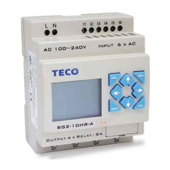
SG2 Model Identification
Explains how to interpret the model number of the SG2 smart relay.
Disclaimer of Liability
States the publisher's disclaimer regarding manual accuracy and potential variances.
Quick Start Setup
A concise guide for initial connection, programming, and operation of the SG2 smart relay.
Install SG2 Client Software
Instructions for installing the necessary SG2 Client software from CD or internet download.
Connect Power to SG2 Smart Relay
Details on wiring diagrams for connecting AC or DC power supply to the SG2 smart relay.
Connect Programming Cable
Steps for connecting the programming cable to the SG2 smart relay and computer.
Establish Communication
Procedure for establishing communication between the SG2 Client software and the SG2 relay.
Write Simple Program
Step-by-step guide to writing a basic program using the SG2 Client software.
Chapter 2: Installation
General Specifications
Provides a detailed overview of the SG2's general technical specifications and capabilities.
Environmental Specifications
Details environmental parameters like enclosure type, temperature, humidity, and vibration.
Digital Inputs
Specifies the electrical characteristics and requirements for digital input signals.
Analog Inputs
Details the specifications and acceptable voltage ranges for analog input signals.
Relay Outputs
Provides specifications for relay output contact material, current rating, and load limits.
Transistor Outputs
Details specifications for transistor outputs, including PWM frequency and current capacity.
Product Specifications Summary
Lists detailed specifications for various SG2 models and expansion modules.
Mounting
Instructions and diagrams for mounting the SG2 smart relay and expansion modules.
DIN-rail Mounting
Specific steps for mounting the SG2 and expansion modules onto a DIN rail.
Direct Mounting
Details on how to mount the SG2 and expansion modules directly using screws.
Wiring
Guidelines and diagrams for proper wiring of I/O signals, power, and loads.
K Type Indicator Light
Explains the status indicated by the SG2's K type indicator light.
Chapter 3: Program Tools
PC Programming Software 'SG2 Client'
Overview of the SG2 Client software, its features, and programming modes (Ladder/FBD).
Installing the Software
Instructions for installing the SG2 Client software from the provided CD or internet download.
Connecting the Software
Steps to connect the SG2 smart relay to the computer using the programming cable.
Start Screen
Describes the initial display of the SG2 Client software and its available functions.
New Ladder Program
Guide to creating a new program in the Ladder Logic development environment.
New FBD Program
Guide to creating a new program using the Function Block Diagram (FBD) environment.
Open Existing File
Procedure for opening previously saved Ladder or FBD program files.
Ladder Logic Programming Environment
Details the environment for programming, testing, and configuring the SG2 using Ladder Logic.
Menus, Icons, and Status Bar
Explains the components of the Ladder programming interface: menus, toolbars, and status displays.
Simulation Mode
Describes the built-in simulator for testing and debugging programs without a controller.
Establish Communication
Step-by-step procedure for establishing communication between PC and SG2 smart relay.
Writing Program to Smart Relay
Instructions on how to write a created program to the connected SG2 smart relay.
Online Monitoring/Editing
Features for monitoring and editing programs online, including I/O forcing and mode changes.
Operation Menu
Details system configuration functions available in the Operation menu for online and offline setup.
HMI/TEXT Editing
Details the HMI/TEXT editor and interface for parameter settings and SMS alarm functions.
HMI/TEXT and Keypad Input Example
Demonstrates HMI/TEXT functionality and Z keypad input usage with an example.
Program Documentation
Features for documenting programs using Symbols and Line Comments for I/O labeling and section notes.
Symbol Editing
Explains how to access and use the Symbol editing environment for documenting memory types.
Line Comments Editor
Details how to use the Line Comment editor via the Ladder Toolbar W icon.
Analog Output Set Configuration
Describes the AQ editing environment for setting analog output modes and preset values.
3-Contact/5-Contact Edit Modes
Explains the 3-contact and 5-contact edit modes available in SG2 LADDER mode.
Data Register Set Configuration
Details how to set Data Register contents as unsigned or signed, and configure preset values.
Special DR Register Functions
Explains the function of special DR coils (DR65~DRF0) and their use as special registers.
View Menu Options
Details the software display options available in the View menu for usage lists and status monitoring.
FBD Programming Environment
Introduces the environment for programming and testing the SG2 using Function Block Diagram (FBD).
FBD Interface: Menu, Icons, Status Bar
Explains the menu options, toolbars, and status bar within the FBD programming environment.
FBD Programming Methods
Describes programming techniques in FBD, including drag-and-drop and using mouse/keyboard.
FBD Simulation Mode
Details the FBD simulation test function and its display characteristics.
FBD Online Monitoring/Editing
Features for online monitoring and editing of FBD programs, including I/O forcing and mode changes.
Symbol and Parameters List
Explains how to list FBD symbols and parameters, including editing comments.
Memory Cartridge (PM05 3rd)
Information on the optional PM05 (3rd) memory cartridge for transferring programs between relays.
LCD Display and Keypad Overview
Overview of the built-in LCD display and keypad functions for timer/counter set points and mode changes.
Original Screen Display
Details the original screen display of the SG2 LCD, including button functions and mode navigation.
Chapter 4: Parameter Passing
SG2 Inner Data Type
Explains that all data stored in the SG2 inner system are integers, with decimal points added for display.
Passing Parameter Out of Range
Explains how SG2 handles parameters passed out of their defined range, using upper or lower limits.
Chapter 5: Relay Ladder Logic Programming
Basic Elements in Ladder Logic
Introduces fundamental symbols and their corresponding input, output, coil, and contact types.
Specialty Elements in Ladder Logic
Details specialized elements like expansion coils, edge triggers, RTC, HMI, PWM, and IO Link.
Output Instructions (Latch, Unlatch, Pulse)
Explains Set (Latch), Reset (Unlatch), and Pulse (Flip-Flop) output instructions.
Analog Elements and Functions
Lists analog input, output, and control functions like AS, MD, PID, MX, AR, DR, and MU.
Timer Instructions
Details the 31 Timer coils, their 8 operation modes, and configuration parameters.
Counter Instructions
Explains the 31 Counter coils, their 9 operation modes, and configuration parameters.
Real Time Clock (RTC) Instructions
Details the 31 RTC coils, their 5 operation modes, and 10 configuration parameters.
Comparator Instructions
Explains the 31 comparator coils, their 8 operation modes, and 5 configuration parameters.
HMI Display Instructions
Details the 31 HMI instructions for displaying information on the SG2's LCD screen.
PWM Output Instruction (DC Transistor Models)
Describes the PWM output capability on Q01 and Q02 terminals for 8-stage PWM waveforms.
IO Link/Remote I/O Instruction
Details how to link SG2 units for IO Link network and configure Remote I/O for master/slave setups.
MU (Modbus) Instruction
Explains MU function for Modbus RTU communication at RS485 port, including modes and parameters.
SHIFT (Shift Output) Instruction
Describes the SHIFT coil for sequentially switching serial coils based on input pulse triggers.
AQ (Analog Output) Instruction
Details the AQ instruction for analog output modules, supporting 0-10V or 0-20mA signals.
AS (Add-Subtract) Instruction
Explains the AS function for performing simple integral math calculations: Addition and Subtraction.
MD (MUL-DIV) Instruction
Details the MD function for performing Multiplication and Division calculations.
PID (Proportional-Integral-Differential) Instruction
Explains the PID function for control loops, including its compute formula and parameters.
MX (Multiplexer) Instruction
Describes the MX function that selects one of four preset values based on control coils S1 and S2.
AR (Analog-Ramp) Instruction
Details the AR function for changing current level to target level at a specified rate.
DR (Data Register) Instruction
Explains the DR function for transferring data and holding values.
Chapter 6: FBD Block Diagram Programming
FBD Instructions Overview
Lists instructions for FBD programming, including input, output, auxiliary coils, and logic blocks.
FBD System Memory Space Allocation
Shows memory usage and limitations for different function blocks in FBD programming.
Analog Function Blocks
Covers analog input, expansion analog input, and their use as preset values for other blocks.
Analog Output (AQ) Function Block
Details the AQ instruction for analog output modules, supporting 0-10V or 0-20mA signals.
Coil Block Instruction
Explains output coils (Q, Y, M, N, H, L, P, S) and their manipulation in FBD.
HMI Function Block
Describes HMI instructions for displaying information on the SG2's LCD screen using different text modes.
PWM Function Block (Transistor Output)
Details the PWM output capability on Q01/Q02 terminals for 8-stage PWM waveforms.
FBD System Memory Space Allocation
Shows memory usage and limitations for different function blocks in FBD programming.
Logic Block Instructions
Explains various logic blocks like AND, NAND, OR, XOR, NOT, PULSE, BOOLEAN, and their FBD/LADDER diagrams.
Analog Input Function Blocks
Covers analog input modules (4AI), their registers, and how values are displayed.
Analog Output (AQ) Function Block
Details the AQ instruction for analog output modules, supporting 0-10V or 0-20mA signals.
Coil Block Instruction
Explains output coils (Q, Y, M, N, H, L, P, S) and their manipulation in FBD.
HMI Function Block
Describes HMI instructions for displaying information on the SG2's LCD screen using different text modes.
PWM Function Block (Transistor Output)
Details the PWM output capability on Q01/Q02 terminals for 8-stage PWM waveforms.
Timer Function Blocks
Explains the 250 Timer function blocks in FBD mode, covering modes 0-7 and parameters.
Common Counter Function Blocks
Details common counter function blocks in FBD mode, covering modes 0-6 and parameters.
RTC Comparator Function Blocks
Explains RTC comparator function blocks in FBD mode, covering modes 0-4.
Analog Comparator Function Blocks
Details analog comparator function blocks in FBD mode, covering modes 0-7 and parameters.
AS (Add-Subtract) Function Block
Explains the AS function block for performing Addition and Subtraction calculations.
MD (Multiply-Divide) Function Block
Details the MD function block for performing Multiplication and Division calculations.
PID (Proportional-Integral-Differential) Function Block
Explains the PID function block for control loops, including its compute formula and parameters.
MX (Multiplexer) Function Block
Describes the MX function block that selects one of four preset values based on selection coils S1 and S2.
AR (Analog-Ramp) Function Block
Details the AR function block for changing current level to target level at a specified rate.
DR (Data-Register) Function Block
Explains the DR function block for transferring data and holding values.
MU (Modbus) Function Block
Details the MU function block for Modbus RTU communication, including modes and parameters.
Chapter 7: Hardware Specification
Normal Specification
Details general specifications covering program modes, environment, main machine, noise, installation, and wiring.
Product Specifications Summary
Lists product specifications for various SG2 models, including input power, I/O, and module capabilities.
Power Circuitry Diagram
Illustrates the power circuitry for AC 10/20 points, DC 12V/24V, and mainframe/expansion/communication modules.
Input Specifications Overview
Details input specifications for 100-240V AC and 24V AC models, including circuitry and response times.
100~240V AC Model Input Specifications
Specifies input parameters for the 100-240V AC models, covering signal current and response times.
24V AC Model Input Specifications
Details input parameters for the 24V AC models, including signal current and response times.
24V DC, 12 I/O Model Specifications
Provides specifications for the 24V DC, 12 I/O model, including input circuitry and voltage ranges.
24V DC, 20 I/O Model Specifications
Details specifications for the 24V DC, 20 I/O model, covering input circuitry and response times.
12V DC, 12 I/O Model Specifications
Provides specifications for the 12V DC, 12 I/O model, including input circuitry and voltage ranges.
12V DC, 20 I/O Model Specifications
Details specifications for the 12V DC, 20 I/O model, covering input circuitry and response times.
Output Specifications
Provides specifications for relay and transistor outputs, including load limits and response times.
Light Load Considerations
Addresses surging current issues with light loads and suggests using resistance for mitigation.
Inductance Load Considerations
Explains methods to absorb surging voltage from inductance loads for relay models.
Life of Relay
Provides information on relay life expectancy influenced by temperature and current.
SG2 Size Diagrams
Illustrates the physical dimensions of the SG2 smart relay for 10/12 points and 20 points models.
Chapter 9: Expansion Module
Expansion Module Summarize
Lists available Digital IO, Analog, and Communication expansion modules for the SG2.
Expansion Module Power Specifications
Lists input voltage, current, and power consumption for various expansion modules.
Expansion Module Size
Provides dimensional drawings for the expansion modules, indicating they share the same size.
Digital IO Module Configuration
Explains how to set the number of expansion IO when connecting digital IO modules.
Analog Input Module 4AI
Details the 4-channel, 12-bit analog input module (4AI), its registers, and input signal modes.
Temperature Input Module 4PT
Describes the 4-channel, 12-bit temperature input module (4PT) and its corresponding registers.
Analog Output Module 2AO
Details the 2-channel, 12-bit analog output module (2AO) and its output signal configurations.
MBUS Module Configuration
Explains the MBUS module for RS485 Modbus protocol communication, acting as a slave.
DNET Module Functionality
Details the DNET module for working in DeviceNet networks, supporting master/slave connections.
PBUS Module Functionality
Explains the PBUS module for ProfiBus DP network communication, acting as a gateway and slave node.
EN01 (TCP/IP) Module Configuration
Details the EN01 module for working in TCP/IP networks, enabling read, write, and monitor functions.
Appendix: Keypad Programming
Keypad Programming in Ladder Mode
Step-by-step instructions for programming the SG2 using the keypad in Ladder mode.
Keypad Programming in Ladder FUNCTION BLOCK
Detailed guide for keypad programming within the Ladder FUNCTION BLOCK environment.
Need help?
Do you have a question about the SG2-10HR-A and is the answer not in the manual?
Questions and answers