
Related Manuals for TECO SG2 PLR


Summary of Contents for TECO SG2 PLR
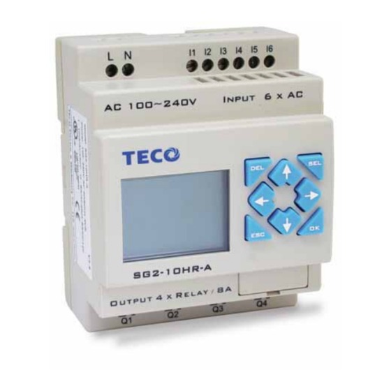
- Page 1 SG2 PLR USER Manual SG2 Programmable Logic Relay ™ 1-800-972-0436 FACTORYMATION...
-
Page 2: Table Of Contents
Data Link/Remote I/O Instruction (SG2-20Vxx Models Only) ......55 SG2 PLR User Manual... - Page 3 Analog comparator Function Block ..........66 ™ SG2 PLR User Manual...
-
Page 4: Chapter 1: Getting Started
Always switch off power before you wire, connect, install, or remove any module. The wiring for the SG2 PLR is open and exposed. For the open-board models, all electrical components are exposed. For this reason, it is recommended the SG2 PLR be installed in an enclosure or cabinet to prevent accidental contact or exposure to the electrical circuits and components. -
Page 5: Examination Before Installation
• Check to see if the model number of the SG2 matches the model number that you ordered. • Check to see whether any damage occurred to the SG2 during shipment. Do not connect the SG2 PLR to the power supply if there is any sign of damage. -
Page 6: Quick Start Setup
1. Install SG2 Client Software Install the SG2 Client Software from CD or from the free internet download at www.factorymation.com 2. Connect Power to SG2 PLR Connect power to the PLR using the below wiring diagrams for AC or DC supply for the applicable models. - Page 7 Remove the plastic connector cover from the SG2 using a flathead screwdriver as shown in the figure below. Insert the plastic connector end of the programming cable into the SG2 PLR as shown in the figure below. Connect the opposite end of the cable to an RS232C serial port on the computer.
- Page 8 OK button. See Chapter 4: Ladder Programming instructions for complete instruction set definitions. Note: If the ladder toolbar is not visible at the bottom of the screen, select View>Ladder Toolbar from the menu to enable. SG2 PLR User Manual...
- Page 9 Select the “Q” coil icon from the ladder toolbar and drop it on the right most cell. Select Q1 from the dialog and press OK as shown below. See Chapter 4: Ladder Programming instructions for complete instruction set definitions. ™ SG2 PLR User Manual...
- Page 10 Test the simple program. From the Operation menu, select the Write function and write the program to the connected PLR as shown below. Select the RUN icon from the toolbar, and select “No” when the pop-up message asks “Do you want to read program from module?”, as shown below. SG2 PLR User Manual...
- Page 11 From the Input Status dialog, click on M1 to activate the contact M1 which will turn ON the Output Q1, as shown below. The highlighted circuit will show active and the first Output (Q1) on the connected PLR will be ON. See Chapter 3: Programming Tools for more detailed software information. ™ SG2 PLR User Manual...
-
Page 12: Chapter 2: Installation
8-point:190g PWM max. output frequency 0.5kHz (1ms on,1ms off) 20-point: 345g Standard max. output frequency 100Hz Agency Approvals cUL , CE, UL Voltage specification 10-28.8VDC Current capacity Resistive: 0.5A/point Maximum Load Inductive: 0.3A/point Minimum Load 0.2mA SG2 PLR User Manual... -
Page 13: Product Specifications
8 Relay SG2-10CR-A 6 AC 4 Relay 85-240VAC SG2-20CR-A 12 AC 8 Relay Accessories SG2-PL01 SG2 Programming Cable SG2-PM05 SG2 Memory cartridge SG2-SW SG2 Programming software. Available on CD or FREE via download from Web ™ SG2 PLR User Manual... -
Page 14: Mounting
Mounting DIN-rail Mounting The SG2 PLR should always be mounted vertically. Press the slots on the back of the SG2 and expansion module plug CONNECTOR onto the rail until the plastic clamps hold the rails in place. Then connect the expansion... - Page 15 A1 A2 X3 X4 Input 4×AC M4X20(#8x32) AC 100~240V DC 24V Input 8 x DC(A1,A2 0~10V) SG2-8ER-A SG2-12HR-D Output 4 x Relay / 8A CONNECTOR Output 4 x Relay / 8A ™ SG2 PLR User Manual SG2 PLR User Manual...
-
Page 16: Wiring
AC ..V Input ..DC ..V DC ..V Input ..Input ..AC (100-240V) OUTPUT 4 x TR / 0.5A Output 4 x Relay / 8A Output Terminals 12...240V 50/60 Hz or 12...125V 12...240V 50/60 Hz SG2 PLR User Manual... - Page 17 INPUT ..Output Terminals Output 8 x Relay / 8A OUTPUT 8 x TR / 0.5A 12...240V 50/60 Hz or 12...125V Sensor Connection 3-wire, PNP only I1 I2 I3 I4 I6 A1 2-wire DC V Input ™ SG2 PLR User Manual...
- Page 18 Only short circuit the first and the last module. In accordance to EIA RS-485 standard, DATA LINK can connect Max.8 Modules (ID:1-8). REMOTE I/O can only connect 2 modules (MASTER & SLAVE). A1 A2 RS485 RS485 RS485 SG2 PLR User Manual...
-
Page 19: Chapter 3: Program Tools
4. The Simulation Mode allows users to run and test their program before it is loaded to the controller. 5. Real-time communication allows the user to monitor and force I/O on the SG2 PLR operation during RUN mode. Installing the Software Install the SG2 Client Software from CD or from the free internet download at www.factorymation.com... - Page 20 The Ladder Logic Programming Environment includes all the functions for programming and testing the SG2 PLR using the Ladder Logic programming language. To begin a new program select File-->New--> and select the desired model of SG2, and the number of connected expansion units if applicable, as shown below.
- Page 21 5. Current Mode – operation mode of the controller, or simulator, from the connected PC. 6. Ladder Toolbar – Icons for selecting and entering all available Ladder Logic instructions. 7. Status Bar – Status of current open project and connected PLR. ™ SG2 PLR User Manual...
- Page 22 Below is an example of some common methods of entering programming instructions. The “A” and “L” keys or icons are used to complete parallel and serial circuits. The rightmost column is for output coils. SG2 PLR User Manual...
- Page 23 Establish Communication The following is the simple procedure for establishing communication between the connected PC and the SG2 PLR. Select “Operation/Link Com Port…” as shown below. ™ SG2 PLR User Manual...
- Page 24 The SG2 Client software will then begin to detect the connected PLR to complete it’s connection as shown below. Writing Program to PLR From the Operation menu, select the Write function and write the program to the connected PLR as shown below. SG2 PLR User Manual...
- Page 25 Additional online functions include, I/O forcing, and Mode changes (Run/Stop/Quit). Note: The SG2 Client software does not support runtime logic editing changes. All logic edits to contacts, coils, timers/counters, and circuit connecting lines must be written to the connected PLR while in Stop mode. ™ SG2 PLR User Manual...
- Page 26 The Symbol editing environment can be access through the menu using the Edit>Symbol… selection or using the symbol icon on the main toolbar shown below. The Symbol editing environment allows for documenting all the contact and coil memory types, and selecting display modes as shown below. Line Comments SG2 PLR User Manual...
-
Page 27: Memory Cartridge
2. Insert the PM05 memory cartridge onto the connector as shown above. 3. From the display keypad on the face of the SG2 PLR, select either WRITE (to PM05) or READ (from PM05) to transfer the program to or from the PLR to the PM05 memory cartridge. -
Page 28: Lcd Display And Keypad
When in a ladder display screen, press the ESC to display the main menu. Delete – Used to delete an instruction or rung from the ladder program. The 4 navigation buttons are used to move the cursor throughout the functions of the SG2 display or active program. SG2 PLR User Manual... -
Page 29: Chapter 4: Relay Ladder Logic Programming
In this example, when input I3 turns on, timer T1 will start. When the timer reaches the preset of 5 seconds timer status contact T1 turns on. When T1 turns on, output Q4 turns on. Turning off I3 will reset the timer. ™ ™ SG2 PLR User Manual... - Page 30 Expansion input coil 12 (X1-XC /x1-xC) Expansion output coil 12 (Y1-YC / y1-yC) Differential (one shot) D (Positive) d (Negative) 15 (R1-RF / r1-rF) Analog comparator 15 (G1-GF / g1-gF) 15 (H1-HF) 1 (P1) DATA LINK 8 (L1-L8) SG2 PLR User Manual...
-
Page 31: Specialty Memory Types
A negative input differential instruction, or One-Shot, holds its status ON for one CPU scan when the preceding series contact transitions from ON to OFF. This transition from ON to OFF is called a Negative Input Differential. ™ SG2 PLR User Manual... -
Page 32: Output Instructions
OFF to ON. Once the output is OFF or reset, it will remain OFF until it is reset using another output instruction. It is not necessary for the preceding input contact controlling the Reset output instruction to remain ON. SG2 PLR User Manual... - Page 33 Pushbutton I3 is pressed and released Motor Q4 will turn ON and remain on. When Pushbutton I3 is pressed again, Motor Q4 will turn OFF and remain OFF. The pulse output instruction (P) will “flip-flop” its state from ON to OFF at each press of Pushbutton I3. ™ SG2 PLR User Manual...
-
Page 34: Counter Instructions
Chapter 4: RLL Programming Counter Instructions The SG2 PLR includes a total 15 separate counters that can be used throughout a program. Each counter has a choice of 8 operation modes, 6 for general purpose counting and 2 for high speed counting. - Page 35 PLR. In the example below, the counter will stop counting when it reaches the preset value of 20. Counter status bit C1 will be ON when the current value is 20. ™ SG2 PLR User Manual...
- Page 36 Additionally, the current count value is non-retentive and will reset to zero on a loss of power to the PLR. In the example below, the counter will continue counting after its preset value of 20. Counter status bit C1 will be ON when the current value is 20. SG2 PLR User Manual...
- Page 37 PLR. In the example below, the counter will continue counting after its preset value of 20. Counter status bit C1 will be ON when the current value is 20. ™ SG2 PLR User Manual...
- Page 38 Additionally, the current count value is non-retentive and will reset to zero on a loss of power to the PLR. In the example below, the counter will continue counting after its preset value of 20. Counter status bit C1 will be ON when the current value is 20. SG2 PLR User Manual...
- Page 39 Additionally, the current count value is retentive and will keep its current count after a loss of power to the PLR. . In the example below, the counter will continue counting after its preset value of 20. Counter status bit C1 will be ON when the current value is 20. ™ SG2 PLR User Manual...
-
Page 40: High Speed Counters (Dc Version Plrs Only)
Counter Coil Number (C1 ~ CF total: 15 counters) The figure to the right shows the relationship between the numbered block diagram for a Mode 7 Counter, the ladder diagram view, and the software Edit Contact/Coil dialog box. SG2 PLR User Manual... - Page 41 Counter Coil Number (C1 ~ CF total: 15 counters) The figure to the right shows the relationship between the numbered block diagram for a Mode 8 Counter, the ladder diagram view, and the software Edit Contact/Coil dialog box. ™ SG2 PLR User Manual...
-
Page 42: Timer Instructions
Timer Instructions The SG2 PLR includes a total of 15 separate timers that can be used throughout a program. Each timer has a choice of 7 operation modes, 6 for general purpose timing and 1 (mode 7) for a pulse timer. - Page 43 PLR. The timer reset input is Input I 1. In the example below, the timer will stop timing when it reaches the preset value of 5 seconds. Timer status bit T1 will be ON when the current value is 5. ™ SG2 PLR User Manual...
- Page 44 T1 will be ON immediately when its rung is true. The timer will only begin timing up when its rung changes to false. Timer status bit T1 will turn OFF when the current time value reaches 10 seconds. SG2 PLR User Manual...
- Page 45 Also in the example below, the timer status bit T1 will turn ON only after its rung transitions from true to false. Timer status bit T1 will turn OFF when the current time value reaches 10 seconds. ™ SG2 PLR User Manual...
- Page 46 T1 will be ON immediately when its rung is true and begin its timing sequence. Timer status bit T1 will turn OFF when the current time value reaches its preset of 10 seconds. This Flash sequence of the timer status bit T1 will continue as long as its rung remains true. SG2 PLR User Manual...
- Page 47 Timer status bit T1 will turn OFF when the current time value reaches its preset of 5 seconds. This Flash sequence of the timer status bit T1 will continue as long as its rung remains true. ™ SG2 PLR User Manual...
- Page 48 This type of cascade timer is of ten used in combination with a counter in applications where it is necessary to count the number of time cycles completed. Note: Timer Mode 7 uses two timers. These timers cannot be reused as timers for other modes in other areas of the program. SG2 PLR User Manual...
-
Page 49: Real Time Clock (Rtc) Instructions
Chapter 4: RLL Programming Real Time Clock (RTC) Instructions The SG2 PLR includes a total of 15 separate RTC instructions that can be used throughout a program. Each RTC instruction has a choice of 3 operation modes, and has 10 parameters for proper configuration. The initial clock/calendar setting for each connected SG2 is set using the Operation»RTC Set menu selection from the SG2 Client software. - Page 50 RTC mode 3, Year-Month-Day Setting RTC Year ON Setting RTC Year OFF Display RTC Present time: Year-Month-Day Setting RTC month ON Setting RTC Day ON Setting RTC month OFF Setting RTC Day OFF RTC Code (R1~RF, total 15 group) SG2 PLR User Manual...
-
Page 51: Comparator Instructions
Chapter 4: RLL Programming Comparator Instructions The SG2 PLR includes a total of 15 separate comparator instructions that can be used throughout a program. Each comparator has a choice of 5 operation modes. Additionally, each comparator has 7 parameters for proper configuration. The table below describes each configuration parameter, and lists each compatible memory type for configuring counters. - Page 52 In this example below, Mode 5 is the selected function that compares the value of Counter (C1) to a constant value (N) of 15 counts (the decimal point is ignored). Status coil G1 turns ON if C1 is to 15 counts. SG2 PLR User Manual...
-
Page 53: Hmi Display Instructions
Chapter 4: RLL Programming HMI Display Instructions The SG2 PLR includes a total of 15 HMI instructions that can be used throughout a program. Each HMI instruction can be configured to display information on the SG2 12×4 character LCD in text, numeric, or bit format for items such as... -
Page 54: Pwm Output Instruction (Dc Transistor Output Models Only)
Input Selected Stage 2(I1~gF) Set stage 3 Input Selected Stage 3(I1~gF) Set stage 4 Set PWM pulse width (0~32768ms) Set stage 5 Set PWM Period(1~32768ms) Set stage 6 PWM output terminal P1 Set stage 7 Set stage 8 SG2 PLR User Manual... -
Page 55: Data Link/Remote I/O Instruction (Sg2-20Vxx Models Only)
The Data Link instruction below is setup for Mode 1 Send where the Master PLR is sending 5 I/O points of Inputs to each connected Slave PLR. The starting Input is I03 with the resulting range of 5 sending inputs equal to I3 – I7. ™ SG2 PLR User Manual... - Page 56 I3, set as start from W17, when enabling the Data Link, the state ‘ON/OFF’ of I3~I7 is controlled by the state of memory list position W17~W21- , which is irrelative to the actual state of input terminal. SG2 PLR User Manual...
-
Page 57: Chapter 5: Function Block Diagram Programming
Expansion Input X01~X0C(12) Output Q01~Q08(8) Expansion Output Y01~Y0C(12) Auxiliary M01~M0F(15) Knob N01~N0F(15) H01~H0F(15) P01(1) SHIFT S01(1) I/O LINK L01~L08(8) Logic /Function Block B01~B99(99) Normal ON Normal OFF No Connection Coil Block Instruction Logic Block Instructions ™ ™ SG2 PLR User Manual... -
Page 58: Pwm Function Block
The PWM output terminal ‘Q1’ can output 8 PWM waveforms. (only provided for transistor output version) SHIFT Function Block Symbol Description SHIFT code (Total 1 group) Set output type (Q, Y) Set output shift number (1-8) SG2 PLR User Manual... -
Page 59: And Logic Block
Chapter 5: FBD Programming AND Logic Block Ladder AND (Edge) Logic Block Ladder Note: The input terminal is NOP which is equivalent to ‘Hi’ NAND Logic Block Ladder NAND (Edge) Logic Block Ladder ™ ™ SG2 PLR User Manual... -
Page 60: Or Logic
Chapter 5: FBD Programming OR Logic Ladder NOR Logic Ladder Note:The input terminal is NOP which is equivalent to ‘Lo’ XOR Logic Ladder SR Logic Block Ladder SG2 PLR User Manual... -
Page 61: Not Logic Block
Counter Function Block Counter Mode 1 Counting Input Up/Down Counting Reset Counting Parameter Counter Mode 2 Counting Input Up/Down Counting Reset Counting Parameter Note:The “>”means the current value appeared will be greater than present value. ™ ™ SG2 PLR User Manual... -
Page 62: Counter Mode 5
Counter Mode 5 Counting Input Up/Down Counting Reset Counting Parameter Counter Mode 6 Counting Input Up/Down Counting Reset Counting Parameter Note:The “C”means that will keep the current value in 0 during the Reset pin be enable. SG2 PLR User Manual... -
Page 63: High Speed Counter Function Block
Reset Counting Parameter Note: High speed input terminal I1, I2 Timer Function Block Timer Mode 1 (ON-Delay A Mode) Enable Input Timing Parameter Timer Mode 2 (ON-Delay B Mode) Enable Input Reset Timing Parameter ™ ™ SG2 PLR User Manual... - Page 64 Reset Timing Parameter Timer mode 5 (FLASH A Mode) Enable Input Reset Timing Parameter Timer mode 6 (FLASH B Mode) Enable Input Reset Timing Parameter Timer mode 7 (FLASH C Mode) Enable Input Reset Timing Parameter SG2 PLR User Manual...
-
Page 65: Rtc Function Block
Chapter 5: FBD Programming RTC Function Block RTC Mode 1 (Daily) Enable Input RTC Parameter RTC Mode 2 (Weekly) Enable Input RTC Parameter RTC Mode 3 (Year Month Day) Enable Input RTC Parameter ™ ™ SG2 PLR User Manual... -
Page 66: Analog Comparator Function Block
Analog Input Reference Analog Comparison Mode 3 Enable Input Analog Input Analog Input Reference Analog Comparison Mode 4 Enable Input Analog Input Analog Input Reference Analog Comparison Mode 5 Enable Input Analog Input Analog Input Reference SG2 PLR User Manual...
Need help?
Do you have a question about the SG2 PLR and is the answer not in the manual?
Questions and answers