Table of Contents
Advertisement
Quick Links
TECO
SG2 Micro-Controller
Operation Manual
-
+
I1
I2
I3 I4
I5
I6 A1
A2
DC 24V
Input 8 x DC(A1,A2 0~10V)
SG2-12HR-D
Output 4 x Relay / 8A
Q1
Q2
Q3
Q4
-
+
I1 I2
I3 I4
I5
I6 A1 A2
DC 24V
Input 8 x DC(A1,A2 0~10V)
Run
SG2-12KR-D
Output 4 x Relay / 8A
Q1
Q2
Q3
Q4
+
-
I1
I2 I3
I4
I5
I6
I7 I8
A1
DC 24V
Input 12 x DC(A1...A4=0~10V)
SG2-20HR-D
Output 8 x Relay / 8A
Q1
Q2
Q3
Q4
Q5
Q6
+
-
I1
I2 I3
I4
I5
I6
I7 I8
I9
DC 24V
Input 8 x DC
Run
20KT-D
Output 8 x Tra. / 0.5A
T1
T2
T3
T4
T5
T6
Version:First Edition
X1 X2
X3
X4
Input
4 × AC
L
N AC 100~240V
Run
SG2-8ER-A
Output 4 x Relay / 8A
Y1
Y2
Y3
Y4
X1
X2
X3
X4
Input
4 × AC
L
N
AC 100~240V
Run
SG2-8ER-A
Output 4 x Relay / 8A
Y1
Y2
Y3
Y4
A2
A3 A4
Input
4 × AC
SG2-8ER-A
Output 4 x Relay / 8A
Q7
Q8
IA
IB
IC
Input
4 × AC
SG2-8ER-A
Output 4 x Relay / 8A
T7
T8
X1
X2
X3
X4
Input
4 × AC
L
N AC 100~240V
Run
SG2-8ER-A
Output 4 x Relay / 8A
Y1
Y2
Y3
Y4
X1
X2
X3
X4
Input
4 × AC
L
N
AC 100~240V
Run
SG2-8ER-A
Output 4 x Relay / 8A
Y1
Y2
Y3
Y4
X1
X2
X3
X4
X1
X2
X3
Input
4 × AC
L
N
AC 100~240V
L
N
AC 100~240V
Run
Run
SG2-8ER-A
Output 4 x Relay / 8A
Y1
Y2
Y1
Y2
Y3
Y4
Y3
X1
X2
X3
X4
X1
X2
X3
Input
4 × AC
L
N
AC 100~240V
L
N
AC 100~240V
Run
Run
SG2-8ER-A
Output 4 x Relay / 8A
Y1
Y2
Y1
Y2
Y3
Y4
Y3
X4
Y4
X4
Y4
Advertisement
Table of Contents

Subscribe to Our Youtube Channel
Related Manuals for TECO SG2


Summary of Contents for TECO SG2
- Page 1 TECO SG2 Micro-Controller Operation Manual Version:First Edition I3 I4 I6 A1 X1 X2 Input Input 4 × AC 4 × AC N AC 100~240V N AC 100~240V DC 24V Input 8 x DC(A1,A2 0~10V) SG2-8ER-A SG2-8ER-A SG2-12HR-D Output 4 x Relay / 8A...
- Page 2 ◎ 8ER-D Relay ◎ 8ET-D Transisto ◎: YES *: The input points consist of the ones having analog input function. 12-3 Power Supply Standard Discrete Input .12-3-1 AC/DC 24V SG2-10HR-A SG2-20HR-A SG2-20HR-D SG2-12HR-D SG2-10KR-A SG2-20KR-A SG2-20KR-D SG2-12KR-D SG2-10CR-A SG2-20HT-D SG2-12CR-D...
- Page 3 When the power is on, never contact the terminal to avert electrical induction. It is strongly recommended to add the safety protection such as the emergence stop and external interlock circuit to prevent the SG2 from trouble and mechanical damage.
- Page 4 Chapter 1 General Chapter 2 Operation Precaution Chapter 3 System configuration Chapter 4 Installation and wiring Chapter 5 Operation Flow Chapter 6 LADDER Instruction Description Description Chapter 7 FBD Block Chapter 8 System Design Chapter 9 Spare Program Chapter 10 Test Run Chapter 11 Inspection and Maintenance Chapter 12 Technical Specification Chapter 13 20 points V TYPE Function...
-
Page 5: Table Of Contents
List Chapter 1 General-------------------------------------------------------------------------------------------1 Chapter 2 Operation Precaution---------------------------------------------------------------------------3 2-1 Installation Environment-------------------------------------------------------------------3 2-2 Installation-----------------------------------------------------------------------------------3 2-3 Wiring----------------------------------------------------------------------------------------3 2-4 Static Electricity-----------------------------------------------------------------------------3 2-5 Cleanness-------------------------------------------------------------------------------------3 2-6 Storage----------------------------------------------------------------------------------------4 2-7 Over-current Protection--------------------------------------------------------------------4 Chapter 3 System configuration---------------------------------------------------------------------------5 3-1 Basic System Configuration ----------------------------------------------------------------5 3-2 Configuration for computer Connection and Spare Program Cartridge --------------6 Chapter 4 Installation---------------------------------------------------------------------------------------8 4-1 Installation Environment---------------------------------------------------------------------8... - Page 6 Timer mode 4-------------------------------------------------------------------------38 Timer mode 5-------------------------------------------------------------------------39 Timer mode 6-------------------------------------------------------------------------40 Timer mode 7-------------------------------------------------------------------------40 6-3-3 RTC instruction-----------------------------------------------------------------------40 Weekly Mode-------------------------------------------------------------------------40 Year-Month-Day Mode------------------------------------------------------------- 40 Mode 1---------------------------------------------------------------------------41 Mode 2---------------------------------------------------------------------------43 Mode 3---------------------------------------------------------------------------46 6-3-4 Analog Comparator------------------------------------------------------------------47 6-3-5 HMI------------------------------------------------------------------------------------48 6-3-6 PWM Output function-------------------------------------------------------------- 61 6-3-7 I/O Link Function--------------------------------------------------------------------63 6-4 Operation Method---------------------------------------------------------------------------64 6-4-1 Original Screen----------------------------------------------------------------------65 6-4-2 Main Menu---------------------------------------------------------------------------71...
- Page 7 8-1 Procedure for system design-------------------------------------------------------------120 8-2 Consideration for System Design-------------------------------------------------------121 8-3 Code Distribution for Relay--------------------------------------------------------------121 Chapter 9 Spare Program--------------------------------------------------------------------------------122 9-1 Spare Program Cartridge (PM05)------------------------------------------------------- 122 9-2 Computer Write Software (Client)------------------------------------------------------ 123 Chapter 10 Test Run-------------------------------------------------------------------------------------124 10-1 Confirmation before Test Run----------------------------------------------------------124 10-2 Procedure of Test Run-------------------------------------------------------------------125 Chapter 11 Inspection and Maintenance--------------------------------------------------------------126...
-
Page 8: Chapter 1 General
Chapter 1 General SG2 is a tiny smart PLC having 44 points O/I system, applying ladder graphic program and FBD program, and applicable to the small-scale automatic operation. SG2 can expand 3 groups of 4-input-4-output module, one 4AI Module, one communication Module. The smart mobility and supremacy the SG2 inheres are greatest assistance for you to considerably save both time and cost in operation. - Page 9 Feature 4 Ease installation and maintenance (1) Screw installation (2) DIN rail installation (3) Spare program cartridge PM05 (optional) (4) LCD display shows online input and output in operation Feature 5 (1) Multiple outputs: Relay output, Max. 8A/points (resistive load). Transistor output 0.5A/Point(resistive load) (2) It can directly drive 1/3 HP motor.
-
Page 10: Chapter 2 Operation Precaution
◎ In the extremely arid area, the humans’body is susceptible to generate of static electricity. Never touch the SG2 with hands to avert static damage to the SG2. 2-5 Cleanness Use the clean and dry cloth to wipe the surface of the SG2. It is prohibited to clean the SG2... -
Page 11: Storage
The SG2 shall be kept away from the said place. 2-7 Over-current Protection ◎ The SG2 is not incorporated a protective fuse at the output terminal. To avoid the short circuit on the load side, it is recommended to cable a fuse between each output terminals... - Page 12 Content 3-1 Basic configuration 3-2 Configuration of computer connected and spare program cartridge.
-
Page 13: Chapter 3 System Configuration
SG2-8ER-A SG2-12HR-D SG2-12KR-D Output 4 x Relay / 8A Output 4 x Relay / 8A Output 4 x Relay / 8A SG2 10/12 Points: SG2 expand I/O & COMM: Expansion Type Blind Type Bare board Type (economical type) ◎ ◎... -
Page 14: Configuration For Computer Connection And Spare Program Cartridge
3-2 Configuration for computer Connection and Spare Program Cartridge (1) Link the computer and SG2 with Client Cable. Through the Client software, the computer is ready to read and write the programs contained in SG2 and oversee on line operation in SG2. (See the figure below) - Page 15 Figure 3-2-2...
-
Page 16: Chapter 4 Installation
Chapter 4 Installation 4.1 Installation Environment The SG2 PLC is prohibited to be installed under the following environments: ◎ The ambient temperature is beyond -20℃~55 . ℃ ◎ The relative humidity exceeds 5~90%. ◎ Area is brimful of dust, salt and iron powder. -
Page 17: H Type
4-2-1 H-TYPE PRODUCTS: SG2-12H#-D //12H#-12D SG2-20##-D //20##-12D SG2-10HR-A//10HR-24A SG2-20HR-A//20HR-24A WARN: Unintentional equipment operation. The application of this product requires know-how in design and program of control system. Only persons qualified are allowed to program, install and apply this product. Failure to follow this instruction will result in death, serious injury or equipment damage. - Page 18 Cut off all power before maintenance. Electric shock will result in death or serious injury. Input 12/24V DC: I3 I4 I1 I2 I5 I6 A2 A3 DC V Input DC V INPUT SG2-12H# -D SG2-20## -D SG2-12H# -12D SG2-20## -12D...
- Page 19 Input 24V AC or 100…240V AC: I5 I6 I5 I6 AC ..V Input ..AC ..V INPUT ..SG2-10HR-A/10HR-24A SG2-20HR-A/20HR-24A Output (Relay): Output 4 x Relay / 8A Output 8 x Relay / 8A Output (Transistor): OUTPUT 4 x TR / 0.5A...
- Page 20 I/O link or Remote I/O: (Only products, SG2-20VR-D/20VT-D/20VR-12D/20VT-12D are available.) A1 A2 A1 A2 RS485 RS485 RS485 ①-1A quick-blowing fuse, circuit-breaker or circuit protector ②-Surge absorber (36V DC) ③-Surge absorber (400V AC) ④-Fuse, circuit-breaker or circuit protector ⑤-Inductive load ⑥-Only short circuit the first product and the last product ⑦-Comply with standard : EIA RS-485.When I/O link, the net can connect 8 products...
- Page 21 Input 8 x DC(A1,A2 0~10V) DC 24V Input 8 x DC(A1,A2 0~10V) I1 [ T1 [ T2 T1 [Q1 SG2-12HR-D SG2-12HR-D SG2-12HR-D PM05 Output 4 x Relay / 8A Output 4 x Relay / 8A Output 4 x Relay / 8A...
-
Page 22: K Type
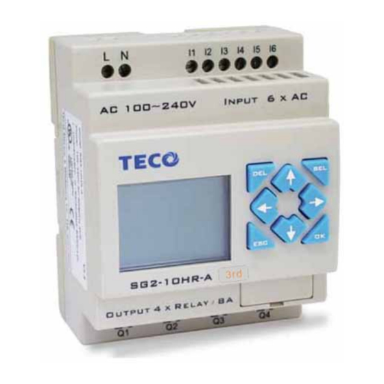
4-2-2 K-TYPE PRODUCTS: SG2-12K#-D //12K#-12D SG2-20K#-D //20K#-12D SG2-10KR-A//10KR-24A SG2-20KR-A//20KR-24A WARN: Unintentional equipment operation. The application of this product requires know-how in design and program of control system. Only persons qualified are allowed to program, install and apply this product. Failure to follow this instruction can result in death, serious injury or equipment damage. - Page 23 I2 I3 I4 I6 I7 IA IB AC 100~240V INPUT 6 x AC AC 100~240V INPUT 12 x AC SG2-10KR-A SG2-20KR-A OUTPUT 4 x RELAY / 8A OUTPUT 8 x RELAY / 8A AC 100~240V INPUT 6 x AC SG2-10KR-A OUTPUT 4 x RELAY / 8A 0.14...1.5...
- Page 24 I5 I6 DC V Input DC V INPUT SG2-12K#-D SG2-20K#-D SG2-12K#-12D SG2-20K#-12D A2 A3 DC V Input Input 24V AC or 100…240V AC: I5 I6 I5 I6 IB IC AC ..V Input ..AC ..V INPUT ..SG2-20KR-A/20KR-24A SG2-10KR-A /10KR-24A...
- Page 25 T1 [Q1 SG2-12KR-D SG2-12KR-D SG2-12KR-D Output 4 x Relay / 8A Output 4 x Relay / 8A SG2 CLIENT V... - Unplug the PM05 cartridge first. - Don’t electrify until the CLIENT CABLE is connected. - Execute SG2 CLIENT software online.
- Page 26 Input 8 x DC(A1,A2 0~10V) DC 24V Input 8 x DC(A1,A2 0~10V) I1 [ T1 [ T2 T1 [Q1 SG2-12KR-D SG2-12KR-D SG2-12KR-D PM05 Output 4 x Relay / 8A Output 4 x Relay / 8A Output 4 x Relay / 8...
-
Page 27: C Type
4-2-3 C-TYPE PRODUCTS: SG2-12C#-D //12C#-12D SG2-20C#-D //20C#-12D SG2-10CR-A//10CR-24A SG2-20CR-A//20CR-24A WARN: Unintentional equipment operation. The application of this product requires know-how in design and program of control system. Only persons qualified are allowed to program, install and apply this product. Failure to follow this instruction will result in death, serious injury or equipment damage. - Page 28 26...18 26...14 26...14 26...16 (0.14in) lb-in DANGER: HAZARDOUS VOLTAGE Cut off all power before maintenance. Electric shock will result in death or serious injury. Input 12/24V DC: I1 I2 I5 I6 I7 SG2-12C# -D SG2-20C# -D SG2-12C# -12D SG2-20C# -12D...
- Page 29 Input 24V AC or 100…240V AC: I1 I2 SG2-10CR-A/10CR-24A SG2-20CR-A/20CR-24A Output (Relay): Output (Transistor): ①-1A quick-blowing fuse, circuit-breaker or circuit protector...
- Page 30 ③-Surge absorber (400V AC) ④-Fuse, circuit-breaker or circuit protector ⑤-Inductive load Communicate with SG2 CLENT Software: I5 I6 SG2 CLIENT V... - Don’t electrify until the CLIENT CABLE is connected. - Connect the CLIENT CABLE. - Execute SG2 CLIENT software online.
-
Page 31: E Type
4-2-4 E type E-TYPE series product SG2-8ER-D/8ET-D SG2-8ER-A SG2-4AI ①Power supply terminals SG2-4AI ②Retractable X1 X2 Input mounting feet 4 × AC INPUT DC 24v 4 × DC ③Input terminal AC 100~240V ④Voltage/Operating mode green signaling ⑤Press-button ⑥Relay output SG2-4AI... - Page 32 X1 X2 Input 4 × AC AC 100~240V SG2-8ER-A Output 4 x Relay / 8A Input I3 I4 I6 A1 4 × AC AC 100~240V DC 24V Input 8 x DC(A1,A2 0~10V) SG2-8ER-A SG2-12HR-D Output 4 x Relay / 8A...
- Page 33 0.14...1.5 0.14...0.75 0.14...2.5 0.14...2.5 0.14...1.5 26...16 26...18 26...14 26...14 26...16 (0.14in) lb-in Danger: Cut off all the power supply before maintenance. Or operator will be damaged for electric shock. 1) Input 24V DC...
- Page 34 I1 V1 C1 PE DC 24v DC 24v SG2-4AI SG2-4AI Input 4 x (0..10V/0..20mA) Input 4 x (0..10V/0..20mA) I2 V2 C2 I3 V3 V4 C4 2) Input 100…240V AC: 3) Output (Relay):...
- Page 35 SG2-8ER-A Output 4 x Relay / 8A 4) Output (Transistor): SG2-8ET-D OUTPUT 4 x TR/0.5A 1A quick-blowing fuse, circuit-breaker or circuit protector - Surge absorber(36V DC) - Surge absorber(400V AC) Fuse, circuit-breaker or circuit protector - Inductive load Note: When Relay output connects with AC inductance load, please parallel...
- Page 36 Input 8 x DC(A1,A2 0~10V) Product switched on,module in run mode Fast flashing (3Hz),module in Fault mode - Date transfer error SG2-8ER-A SG2-12HR-D Output 4 x Relay / 8A - Connecting with front error Output 4 x Relay / 8A...
-
Page 37: Chapter 5 Operation Flow
5~20mS; Under FBD: 2~10mS ◎ The scan time is related to the user’s program capacity. The scan time range is 5~20ms under Ladder edit mode while 2~10ms under FBD mode. Overall Response Time for SG2 (not including expansion module) Chapter 5 Operation Flow... -
Page 38: Dealing In Power Loss
ta: Input OFF -> ON response time tb: one scan time tc: Output OFF-> ON response time 5-2 Operation dealing in power loss Under RUN mode, the present data of counter and the state of the M coil will be memorized as power off. 5-3 RUN-STOP-RUN operation RUN-STOP, present output will be cut and the present value of function block and state of the coils will be cleared. -
Page 39: Basic Instruction
Content 6-1 Basic instruction introduction 6-1-1 Instructions with logical operand 6-1-2 Instructions without logical operand 6-1-3 Conntect signal 6-2 Instruction function example 6-3 Function block 6-3-1 General counter * Counter mode 1 * Counter mode 2 * Counter mode 3 *... -
Page 40: Instructions Without Operand
Chapter 6 LADDER Instruction Description 6-1 Basic Instruction 6-1-1 Instructions with logical operand General RESET Number Normal Normal PULSE output output output output open close contact contact Input coil 12(I1∼IC / i1∼iC) Output coil 8 (Q1∼Q8 / q1∼q8) Auxiliary coil 15(M1∼MF / m1∼mF)... - Page 41 One complete scan period 2: i1─d──[ Q1 i1 is inverse of I1 One complete scan period ◎ NORMAL( -[ )Output I1─── ◎ SET( )Output I1───...
-
Page 42: General Counter
◎ RESET( )Output I1─── ◎ P Output i1─── ON OFF i1 is inverse of I1 6-3 Function Block 6-3-1 General Counter Description Symbol Counting Mode (1- 8) Use (I1 ~ gF) to set counting up or counting down OFF: counting up (0, 1, 2, 3, 4….) ON: counting down ( ….3, 2, 1, 0) Use (I1 ~ gF) to RESET the counting value ON: the counter reset to zero and... -
Page 43: Counter Mode
Note: ※ The setting value of the counter could be a constant or the present value of the timer, counter,analog input A1~A8. ※Foer I1~gF, Input terminal: I1~IC (I1~I12), Output terminal: Q1~Q8, Expansion Input Terminal: X1~XC (X1~X12), Expansion Output Terminal: Y1~YF (Y1~Y12), Counter: C1~CF (C1~C15), Timer: T1~TF (T1~T15), RTC Comparator: R1~RF (R1~R15) , Analog Comparator: G1~GF (G1~G15),Auxiliary Terminal:M1~MF(M1~M15). -
Page 44: Counter Mode 2
Example: (2) Counter Mode 2... -
Page 45: Counter Mode
Note: ※ a. Under this Mode, the counting present value appeared will be greater than 20, unlike the Mode 1 in which the value is locked at 20. b. The present value of counter will be reset to initial (default) value at the time of power ON or switching RUN/STOP. -
Page 46: Counter Mode
(5) Counter Mode 5 Note: a.Under this Mode, the counting present value appeared will be greater than 20, unlike the Mode 1 in which the value is locked at 20. If reset is available, the present value will reset to 0, unrelated with the counting direction. -
Page 47: Counter Mode
be memorized when Run/Stop switching. ◎High Speed Counter (Only Provide for DC Power Supply) DC power supply type has two 1 KHz High speed input terminals, I1 and I2. Two groups of high-speed counting function is available with these two counters. (1) Counter Mode 7 Description Symbol... -
Page 48: Counter Mode
(2) Counter mode 8 Description Symbol Counting Mode(8)—Frequency Comparison High speed counting input terminal: only I1, I2 available. Counting interval time:(0~99.99S) Counter ‘on’ target value (000000~999999) Counter ‘off’ target value (000000~999999) Code of Counter (C1~CF Total :2/15Group, only 2 Groups is available for mode 8, but the counter code is not limited ) 6-10... -
Page 49: Timer
Note: As show in the diagram, the output will be delayed for one interval. 6-3-2 Timer Description Symbol Timer Mode (1-7) Timer Unit:1:0.00~99.99s 2:0.0~999.9s 3:0~9999s 4:0~9999m Use I1~gF to reset the timer value. ON :timer value is reset to Zero and OFF :timer continues to timing Timer present value Timer target value... - Page 50 (M1~M15). The upper case (I1) is Contact ‘a’ while the lower (i1) case is Contact ‘b’. ※The set value of timer can be modified via communication module as MODBUS, PROFIBUS, DEVICENET, TCP/IP. Timer Mode 1(ON-Delay A mode) Sample: 6-12...
- Page 51 6-13...
-
Page 52: Timer Mode
(2) Timer mode 2(ON-Delay B mode) Note: timing begins, the action time of the Relay less than the Minimum unit, will be neglected. (3) Timer Mode 3(OFF-Delay A Mode) 6-14... -
Page 53: Timer Mode
(4) Timer Mode 4(OFF-Delay B Mode) (5) Timer Mode 5(FLASH A Mode) 6-15... -
Page 54: Timer Mode
(6) Timer Mode 6(FLASH B Mode) (7) Timer Mode 7(FLASH C Mode) ※ Note: This is rather special Mode which series connects two timer, t1 and t2. In addition, add PTn, where n=1, 2, 3, 4, ……, E. but Tn + 1 Timer can not be used for other purpose. Sample : I1--------PT1 , t1=T1 Target value;t2=T2 Target value. -
Page 55: Rtc Instruction
6-3-3 RTC Instruction ★ Weekly Mode Symbol Description Input the first week to RTC Input the second week to RTC RTC mode(1~2) 1:daily ,2:consecutive days RTC displays the hour of present time. RTC displays the minute of present time Set RTC hour ON Set RTC Minute ON Set RTC Hour OFF Set RTC Minute OFF... -
Page 56: Mode
(1) RTC Mode 1 Sample 1: : TU-FR : 08:00 : 17:00 Week Monday Tuesday Wednesday … Friday Saturday Sunday Time 8:00 17:00 8:00 17:00 8:00 17:00 8:00 17:00 ENABLE Rn Output ** Note:If ENABLE fails, output is OFF. 6-18... - Page 57 Week Monday Tuesday Wednesday … Friday Saturday Sunday Time 8:00 17:00 8:00 17:00 8:00 17:00 8:00 17:00 ENABLE Rn Output Sample 2: : TU-FR : 17:00 : 8:00 Week Monday Tuesday Wednesday … Friday Saturday Sunday Time 8:00 17:00 8:00 17:00 8:00 17:00...
- Page 58 Sample 4: : FR-MO : 17:00 : 8:00 Week Monday Tuesday … … Friday Saturday Sunday Time 8:00 17: 00 8: 00 17: 00 8: 00 17: 00 8: 00 17: 00 8: 00 17: 00 ENABLE Rn Output Example 5: :...
- Page 59 : SU-SU : 17: 00 : 8: 00 Week Monday Tuesday … … Friday Saturday Sunday Time 8: 00 17: 00 8: 00 17: 00 8: 00 17: 00 8: 00 17: 00 8: 00 17: 00 ENABLE Rn Output (2) RTC Mode 2 Example 1:...
- Page 60 Example 2: : TU-SA : 17:00 : 08:00 Week Monday Tuesday … … Friday Saturday Sunday Time 8:00 17: 00 8: 00 17: 00 8: 00 17: 00 8: 00 17: 00 8: 00 17: 00 ENABLE Rn Output Example 3: :...
- Page 61 Time 8: 00 17: 00 8: 00 17: 00 8: 00 17: 00 8: 00 17: 00 8: 00 17: 00 ENABLE Rn Output Sample 5: : SA-SA : 08:00 : 17:00 Week Monday Tuesday … … Friday Saturday Sunday Time 8:00 17:00...
- Page 62 Sample 1: 03/05/23 04/12/22 Year-Month-Day 2000/01/01 … 2003/05/23 … … 2004/12/22 … 2099/12/30 Time 0:00 0:00 0:00 0:00 ENABLE Rn Output: ** Note:If ENABLE fails, the output will be OFF. Year-Month-Day 2000/01/01 … 2003/05/23 … … 2004/12/22 … 2099/12/30 Time 0:00 0:00 0:00...
-
Page 63: Analog Comparator
2000/01/01 … 2003/05/23 … … 2004/12/22 … 2099/12/30 Time 0:00 0:00 0:00 0:00 ENABLE Rn Output: 6-3-4 Analog Comparator Description Symbol Analog Comparison Mode(1~5) analog input (A1~A8), or the present value of the timer, counter. analog input (A1~A8), or the present value of the timer, counter. - Page 64 PROFIBUS, DEVICENET, TCP/IP. When the relay of analog comparator is ON, there are 5 operation modes described below: ≤ A ≤ A (1) Analog Comparator mode 1 ( A , ⑥ ⑥ ⑦ ≤ A (2) Analog Comparator mode 2 (A ,...
- Page 65 RTC and analog comparator is available via HMI of the controlled equipments. How to use HMI function in SG2 client software will be described in detail, here. ◎Under FBD mode: 1.
- Page 66 Description: (1) To select text Hxx (H01-H0F). If there is no HMI (Text )Block in program ,'NO Hxx' will be displayed here. (2) Text display on LCD; (3) When the Display is enabled, the user can press the SEL button for 3 seconds to show the HMI (Text) Messages (4) To select the 'Unit', the input parameter includes Unit (with Unit display).
- Page 67 Description: ① Function Type ② Number ③ Preset Value ④ Current Value ⑤ Unit B, Counter: Operation mode 1. Text display as follow. Description: ① Function Type ② Number ③ Preset Value ④ Current Value C, RTC mode 1 OR mode 2. Text display as follow. 6-29...
- Page 68 Description: ① Function Type ② Number ③ Preset Value (Start Week) ④ Preset Value (End Week) ⑤ Preset Value (Start time Hour: Minute) ⑥ Preset Value (End time Hour: Minute) ⑦ Current Value (Week, Hour, Minute) 格式化: 項目符號及編號 D. Analog Comparator .Text display as follow. Description: ①...
- Page 69 ⑧ Preset Value E. Ixx (input contact).Text display as follow. Description: ① Function Type ② Number ③ Current Status( ON/OFF) Note: Mxx (Auxiliary output function block), Nxx (auxiliary output function block) is similar to Ixx. 2. Not select the 'Unit'(without Unit display) Under this condition, only the current information of Function Block is displayed.
- Page 70 B. Counter, Counter mode 1.Text display as follow. Description: ① Function Type ② Number C. Analog comparator .Text display as follow. Description: ① Function Type ② Number (5) To select 'Mobile Message'. Hxx displays the mobile number message only. Can’t call out automatically The first line displays input numeral, while the other 3 lines display the Mobile message.
- Page 71 (6) To enable 'Multi Language' to display Multi languages to choose in the character input column. Sample: (7) The option of Chinese (fixed) is available in Chinese Operating System. To select 'Chinese (fixed)', Text Input zone displays 40 fixed Chinese characters which can be set to Text Display Zone.
- Page 72 Using method: Select 'Edit' button to display Chinese editing screen 6-34...
- Page 73 Description: ① Display Chinese to be added. ② Input the Chinese. ③ Press the button 'Add' to add the Chinese to display zone. ④ Select the button 'Ok' to save the edit Chinese data ⑤ Select the button 'Erase' to delete the Chinese the cursor located in the display zone.
- Page 74 Text Hxx LCD displays the text when the master LCD displays the text when the master is 6-36...
- Page 75 is under 'Stop' Mode under 'Run' Mode As the counter is set mode 8, LCD Under 'Stop' mode, the current displays the state of the counter. It will value of text will be marked as '#'. display 'ON' when Run, while 'OFF' when STOP.
- Page 76 Note: (1) When the Display is enabled, the user can press the SEL button for 3 seconds to show the HMI (Text) Messages. (2) This HMI option is for Timer/Counter/Analog/Coil Status display only. When the option is enabled, it will show A1=#.##V, otherwise, it will display #A1#. (3) Select Coil Status I, M, X.
-
Page 77: Hmi
To modify the preset value 000010 of the counter mode 7 as present value of T2 in HMI. Step1:In HMI screen, to press‘SEL’, the cursor blinks in the following location. 0 S e c 5 S e c C 1 = 0 Step2:Press ‘DOWN’... -
Page 78: Pwm Output Function
Step4:Press ‘UP’ 0 S e c 5 S e c C 1 = T 2 Step5:Press ‘OK’ to save the setting. 0 S e c 5 S e c C 1 = T 2 6-3-6 PWM Output Function (only provided for transistor output type.) The transistor output type has a PWM output terminal ‘Q1’, which can output 8-stage PWM waveform. - Page 79 Description Symbol Set display stages (1~8) Display the present stage as operation(0~8) Input Selected Stage 1(I1~gF) Input Selected Stage 2(I1~gF) Input Selected Stage 3(I1~gF) ⑥ Set PWM pulse width (0~32768ms) ⑦ Set PWM Period(1~32768ms) ⑧ PWM output terminal P1 Note: ※...
- Page 80 Set stage 1 Set stage 2 Set stage 3 Set stage 4 Set stage 5 Set stage 6 Set stage 7 Set stage 8 Note:X indicated ON/OFF input terminal is idle. 6-3-7 I/O LINK Function(only provided for 20Vx-X Type) Description Symbol Mode setting (1,2) 1:sending 2:receiving Set the send/receive points(1~8)
- Page 81 list shows. The receiving mode can be selected: W1,W9,W17,W25,W33,W41,W49 and W57. Memory List Location Sending memory Receiving memory W1~W8 W1~W8 W9~W64 W9~W16 W9~W16 W1~W8, W17~W64 W17~W24 W17~W24 W1~W16, W25~W64 W25~W32 W25~W32 W1~W24, W33~W64 W33~W40 W33~W40 W1~W32, W41~W64 W41~W48 W41~W48 W1~W40, W49~W64 W49~W56 W49~W56 W1~W48, W57~W64...
-
Page 82: Operation Method
Sample 2:I/O LINK mode 2 Set ① = 2, ② = 5, set ③ as start from I3, set ④ as start from W17, when enabling the I/O link, the state ‘ON/OFF’ of I3~I7 is controlled by the state of memory list position W17~W21 ④... - Page 83 Press the buttons: ↑ ↓ Move the Cursor Enter the selected language, and display the screen for time setting. (2) Present Time Setting Screen SG2 Edition RTC SET V3.0 00 . 01 . 01 SU 00 : 00 Year. Month. Day...
- Page 84 Press the button: Back to Main Menu Under LADDER Edit Mode, display the state of other relays(expansion SEL+↑ ↓ X&Y⇔M ⇔ T ⇔ C ⇔ R ⇔ G⇔A) ⇔ Original Screen H Function will be displayed as the button is pressed for 3 seconds. If Mode 2 is selected for HMI, the H Function will not be displayed.
- Page 85 SEL+ ↓ SEL+↑ SEL+ ↓ SEL+↑ SEL+ ↓ SEL+↑ SEL+ ↓ SEL+↑ SEL+ ↓ SEL+↑ SEL+ ↓ SEL+↑ 6-47...
- Page 86 ① Expansion display State ② M Display Status: 6-48...
- Page 87 ③ T Display State: ④ C Display State: ⑤ R Display State: ⑥ G Display State: 6-49...
- Page 88 ⑦ Analog Input Value: b) Operation to Display H Function: Press SEL for 3s Display H1 ↓Button ↑Button Display H2 If the target value is displayed, it can be modified. 6-50...
- Page 89 > If the target value is displayed, ↓ Button ↑ Button it can be modified. > If the target value is displayed, it can be modified. ↑ Button ↓ Button If the target value is displayed, it can be modified. If the target value is displayed, it can be modified.
-
Page 90: Main Menu
If the target value is displayed, it can be modified. 6-4-2 Main Menu LCD displays 4-line Main Menu ( 1 ) The Main Menu as SG2 under ‘STOP’ Mode. > LADDER FUN.BLOCK CLEAR PROG. Clear the user program and the... -
Page 91: Main Menu Ladder
Confirm the selected Function Skip to Initial Screen ※SG2 can be modified, edited, cleared and read user program only when it is under STOP Mode. ※As the program is modified, SG2 will automatically backup it to EEPROM. (not PM05) ◎ Main Menu LADDER... - Page 92 2. When the cursor is on Column 8, Press the button to automatically enter the function block and set the parameters(such as T/C)。 SEL+DEL Delete a Line of Instruction. SEL+ESC Display the number of the Lines and operation state of SG2 (RUN/STOP)。 SEL+↑/ ↓ Skip up/ down every 4-line program. SEL+OK Insert a space line Operation Sample:...
- Page 93 Procedure 2 : 6 7 8 Column Press ‘SEL’ Line 1 I 1 (When cursor located at character or digital, press the button to show I1) Procedure 3 : 6 7 8 Column Line 1 Q 1 Press ‘↑’ twice. (Press ‘SEL’...
- Page 94 Procedure 7 : 6 7 8 Column Line 1 q 4 Press ‘←’ (Press ‘SEL’ + ‘← →’ to move the cursor to the position Required revision. Automatically Link Procedure 7 : 6 7 8 Column Line 1 q 4 Press ‘OK’...
- Page 95 (when the cursor located at character and digital, press ‘SEL’ to show ‘ –( Q1’) Auto Add “ -( ” Procedure 10 : 6 7 8 Column Line 1 q 4 M 1 I 3 ( Press ‘OK’ Save the input program data, the position of the cursor will not move.
- Page 96 ┴ (Move the cursor to character in column 3.) Repeat the step 1~7 and key in ‘r 3’ , ─” at Line 2 and column 3~6. Procedure 15 : 6 7 8 Column Line 1 q 4 ┬ M 1 I 3 ( Q 1 Press ‘OK’...
- Page 97 Line 1 q 4 ┬ M 1 I 3 ( Q 1 Press ‘DEL’ ┴ r 3 (to delete the element C7 the cursor locating) Display the present Line the cursor locating and operation state of SG2. 6-59...
- Page 98 Press ‘SEL+ESC’ (simultaneously) ┴ r 3 ( C 7 (The Line 4 displays where the cursor locating and operation state of SG2) 4 S T O P L I N E 0 0 2 Delete the whole Line...
-
Page 99: Function Block Program Input
2 > F U N . B L O C K R U N C L E A R P R O G . The present value will appear when SG2 is under ‘RUN’ mode. Procedure 1: 6 7 8 Column ┌... - Page 100 6 7 8 Column ┌ 1 ┐ Line 1 Never press ‘→’ to move to the 1 ┤ │ digital position. │ 0 0 . 0 0 ├ T 1 (If T2 is required to be changed, Press ‘↑’/‘↓’ and ‘SEL’ ┴...
- Page 101 ┌ 1 ┐ Press ‘OK’ Line 1 1 ┤ │ │ 0 0 . 0 3 ├ T 1 (Save the input data) ┴ ┘ 6 7 8 Column Procedure 2-5: ┌ 1 ┐ Press ‘←’ Line 1 1 ┤ │...
- Page 102 1 ┤ │ │ C 1 ├ T 1 ┴ ┘ Next to step 2-3A, then ‘↑’, the following screen will be shown. step 24A: 6 7 8 column ┌ 1 ┐ Press ‘↑’ line1 1 ┤ │ │ A 2 ├...
- Page 103 ┴ ┘ to change1’ to ‘ 2’) 6 7 8 Column Procedure 2-10: ┌ 1 ┐ Press ‘OK’ Line 1 2 ┤ │ │ 3 3 3 . 3 ├ T 1 (save the input data) ┴ ┘ 6 7 8 Column Procedure 2-11: ┌...
- Page 104 │ 3 3 3 . 3 ├ T 1 (save input data) 4 I 1 ┴ ┘ 6 7 8 Column Procedure 2-15: ┌ 4 ┐ Line 1 Press ‘↓’ for 3 times 2 ┤ │ │ 3 3 3 . 3 ├...
- Page 105 (Press ‘ SEL ’ + ‘ ↑ ↓ ’ to │ 3 3 3 . 3 ├ T 1 change 4 M 4 ┴ ┘ ‘1’ to ‘4’) 6 7 8 Column Procedure 2-20: ┌ 4 ┐ Press ‘OK’ Line 1 2 ┤...
- Page 106 6 7 8 column Step 2-22C: ┌ 4 ┐ Press ‘↑’ line 1 2 A 1 ┤ │ (Move the cursor to 2 to repeat the 3 T 2 │ ├ G 1 above step. ┴ 0 3 . 3 3 ┘...
- Page 107 Last Function Block 6 7 8 Column ┌ 4 ┐ Line 1 2 ┤ │ │ 3 3 3 . 3 ├ T 1 4 M 4 ┴ ┘ Procedure : 6 7 8 Column ┌ 3 ┐ Press ‘SEL+↓’ (Simultaneously) 2 ┤...
-
Page 108: Run Or Stop
│ 0 0 0 0 ├ T 2 4 M 4 ┴ ┘ Move the cursor to change to T , C , R , G, H Step 1: 6 7 8 Column ┌ 2 ┐ Press ‘SEL’ Line 1 2 M 1 ┤... - Page 109 (3) READ (read the program from the PM05 program spare cartridge to SG2 (RAM)) READ >NO When C type or K type machine power up, the program in PM05 will be auto downloaded to the machine and be executed. But there are same exceptional cases: 1.
- Page 110 → Remote Output Y1~Y8 Q1~Q8 (5) RTC Setting RTC SET V3.0 YY . NN . DD SG2 Version MO HH : MM Now Press Begin to input parameters Press ‘SEL’ Move the Cursor + ‘← →’ 1. YY=00~99,NN=01~12,DD=01~31 SEL then 2.MO⇔TU⇔WE⇔TH⇔FR⇔SA⇔SU⇔MO...
- Page 111 Now Press 1. Move downward the Cursor ↑ ↓ 2. Switch the setting screen from A1, A2 to A3, A4. Begin to input parameters Press ‘SEL’ Move the Cursor + ‘← →’ ‘SEL’ + 1. GAIN =000~999 ‘↑ ↓’ 2. OFFSET=-50~+50 Save the Input Data 1.
- Page 112 DEUTSCH German PORTVGVES Portuguese SIMPLIFIED CHINESE Simplified Chinese Now Press Press ‘↑ ↓’ Vertically move the Cursor Select the language the cursor located Back to Main Menu Sample: > ENGLISH √ FRANÇAIS ESPAÑOL ITALIANO ↓key ↑key ENGLISH √ > FRANÇAIS ESPAÑOL ITALIANO ENGLISH...
- Page 113 ESPAÑOL ITALIANO (8)INITIAL INITIAL > LADDER √ Now Press: Press ‘↑ ↓’ Vertically move the Cursor Select the language the cursor located Back to Main Menu The origin program will be cleared as the change of edition method. 6-75...
- Page 114 Content 7-1 Coil Block 7-2 Logic Block 7-3 Function Block 7-3-1 General-purpose Timer Function Block 7-3-2 High-speed Timer Function Block 7-3-3 Timer Function Block 7-3-4 RTC Comparator Function Block 7-3-5 Analog Comparator Function Block 7-4 Block Resource 7-5 FBD Edit Method Chapter 7 FBD Block Description...
-
Page 115: Chapter 7 Fbd Block Description
Chapter 7 FBD Block Description Note: FBD program can only be edited and modified in SG2 Client software and write to SG2 controlled equipments via communication cable. Via controlled equipment, FBD program is available for querying or the parameter of the function block of the program for modifying. - Page 116 (2)PWM Function Block Description Enable → input → → → (3)SHIFT Function Block Description Input terminal description Enable → input → Shift input Setting parameter description: Symbol Description SHIFT code (Total 1 group) Set output type (Q,Y) Set output shift number (1~8) Chapter 7 FBD Block Description...
-
Page 117: Edit Block
Example: Note:When Enable is available, Q1 ON, Q2~Q4 will be OFF, till the first shift input raise edge, Q2 ON, Q1 and Q3~Q5 OFF. The next output coil will be on when meeting the each raise edge and others are OFF. 7-2 Edit Block Chapter 7 FBD Block Description... - Page 118 (1)AND Logic Diagram FBD: LADDER: → I01 And I02 And I03 Note:The input terminal is NOP which is equivalent to ‘Hi’ (2)AND (EDGE) Logic Diagram FBD: LADDER: → I01 And I02 And I03 And D Note:The input terminal is NOP which is equivalent to ‘Hi’...
- Page 119 (4)NAND (EDGE) Logic Diagram FBD: LADDER: → Not(I01 And I02 And I03) And d Note:The input terminal is NOP which is equivalent to ‘Hi’ (5)OR Logic Diagram FBD: LADDER: → I01 or I02 or I03 Note:The input terminal is NOP which is equivalent to ‘Lo’...
- Page 120 Note:The input terminal is NOP which is equivalent to ‘Lo’ (7)XOR Logic Diagram FBD: LADDER: → I01 Xor I02 Note:The input terminal is NOP which is equivalent to ‘Lo’ (8)SR Logic Diagram FBD: LADDER: → Logic I01 I02 Bxx Table holding Note :...
-
Page 121: Function Block
Not I01 Note:The input terminal is NOP which is equivalent to ‘Hi’ (10)Pulse Logic Diagram FBD: LADDER: → Note:The input terminal is NOP which is equivalent to ‘Lo’ 7-3 Function Block The function blocks are classified into 4 sorts: Time, Counter, RTC Comparator ‘R’ and Analog Comparator ‘G’. -
Page 122: Common Counter Function Block
7-3-1 Common Counter Function Block (1) Counter Mode 1 → Counting Input → Up/Down Counting → Reset Counting Parameter → (2) Counter Mode 2 → Counting Input → Up/Down Counting → Reset Counting Parameter → (3) Counter Mode 3 → Counting Input →... -
Page 123: High Speed Counter Function Block
Counting Parameter → (5) Counter Mode 5 → Counting Input → Up/Down Counting → Reset Counting Parameter → (6) Counter Mode 6 → Counting Input → Up/Down Counting → Reset Counting Parameter → 7-3-2 High Speed Counter Function Block (1) Counter Mode 7 →... -
Page 124: Timer Function Block
→ Enable Input Reset Counter Parameter → Note :High speed input terminal I1,I2 7-3-3 Timer Function Block (1) Timer mode 1 (ON-Delay A Mode) → Enable Input Timing Parameter → (2) Timer mode 2 (ON-Delay B Mode) → Enable Input →... -
Page 125: Rtc Comparator Function Block
→ Enable Input → Reset Timing Parameter → (5) Timer mode 5(FLASH A Mode) → Enable Input Timing Parameter → (6) Timer mode 6(FLASH B Mode) → Enable Input → Reset Timing Parameter → (7) Timer mode 7(FLASH C Mode) →... -
Page 126: Analog Comparator Function Block
→ Enable Input RTC Parameter → (2) RTC Mode (Continuous) → Enable Input RTC Parameter → (3) RTC Mode 3 (Year Month Day) → Enable Input RTC Parameter → 7-3-5 Analog comparator Function Block (1) Analog Comparison Mode 1 → Enable Input →... -
Page 127: Fbd Block Resource
→ Analog Input → Analog Input Reference → (3) Analog Comparison Mode 3 → Enable Input → Analog Input → Analog Input Reference → (4) Analog Comparison Mode 4 → Enable Input → Analog Input Reference → (5) Analog Comparison Mode 5 →... -
Page 128: Fbd Edit Method
Block Comparator Comparator Total Memory Logic Block Timer Mode 1~6 Timer Mode 7 Counter Mode 1~8 RTC Comparator Mode 1~3 Analog Comparator Mode 1~5 Sample for calculate the memory in using: When the FBD program contains 2 AND, 1 OR (Logic Block), 2 Timers Mode 1, 1 Counter Mode 7, RTC comparator Mode 1(Function Block), the total Diagram Blocks used are 2+1+2+1+1=7, and the remained is 99-7=92. - Page 129 Original Screen Press for 3s, H function content will be displayed, except the Mode 2 is selected in HMI. Sample: a) operation for displaying the state of other relay.。 ↓key ↑ key ↓key ↑key ↓ key ↑ key ↓ key ↑...
- Page 130 ① Expansion Display State ② M Display State: Chapter 7 FBD Block Description...
- Page 131 ③ N Display State: ④ Analog input b) Operation for displaying H Function Block. Press ‘SEL’ for 3s Display H1 Chapter 7 FBD Block Description...
- Page 132 ↓Key ↑Key Display H2 The displayed values can be modified. > ↓Key ↑Key > ↑Key ↓Key > > Chapter 7 FBD Block Description...
-
Page 133: Main Menu Screen
WRITE READ Similar to Ladder Edit Mode. RTC SET ANALOG SET PASSWORD LANGUAGE INITIAL ( 2 ) When SG2 is under RUN mode, the main selection displays: > FBD PARAMETER STOP WRITE RTC SET Similar to Ladder Edit method. WRITE... -
Page 134: Output Coil Display
(1) Output coil display Now Press ← → ⇔ ⇔ 1. Move the cursor is Bxx, press ‘ ←’ to enter Bxx screen ↑ ↓ 1. Modify the code- (Q : 01~08 , Y : 01~0C , M ,N , H : 01 ~ 0F , L : 01~08 , P : 01 ,S : 01) (Q⇔Y⇔M⇔N⇔H⇔L ⇔P⇔S 2. - Page 135 Press ‘ ↑’ twice to ━ ━ ━ ━ modify Q as M Press ‘ ↓’ twice to ━ ━ ━ ━ recover M as Q Procedure (1)-4 Press ‘ →’ ━ ━ ━ ━ ━ ━ ━ ━ Procedure (1)-5 Press ‘...
-
Page 136: Nr Input Terminal Screen
Screen(such diagram is only available for query, display (2) Nr Input terminal the Nr input contact of FBD program in SG2 Client software.) Now Press 1. Press ←: ⇒ ;press →: ⇒ ; ← → is Bxx, press ← to enter Bxx screen 2. - Page 137 Press ‘ ←’ Enter B02 screen (3) Display Screen for Bn input terminal(such diagram is only available for query, display the Bn input contact of FBD program in SG2 Client software.) Now press ↑ ↓ Press ↑ ↓: the cursor ⇔...
-
Page 138: Hmi Setting Screen
Press ‘ ↓’ twice Procedure (3)-2 Press ‘OK’ 2 : R Enter Parameter setting screen Refer to 2 Parameter of Main Menu (4) HMI Setting Screen Now press Edit the mode SEL + ↑ ↓ Modify the mode (1~2) Save the modified mode after press ‘SEL’. 1. -
Page 139: Pwm Setting Screen
Now press ← → ↑ ↓ ⇔ ⇔ Move the cursor Begin to edit SEL + 1. Modify the mode (1~2) ↑ ↓ 2. modify the terminals point (1~8) modify the send/ receive terminals (I01~I0C,X01~X0C,Q01~Q08, Y01~Y0C,M01~M0F,N01~N0F) Save the modified content after press ‘SEL’ 1.Cancel the modified content after press ‘SEL’... -
Page 140: Shift Setting Screen
1.Cancel the modified content after press ‘SEL’ 2. Back to edit screen (1) for coil ◎ PARAMETER of Main Menu (All the parameter of the used function block in editing FBD program with SG2 Client software can be queried and modified.) Chapter 7 FBD Block Description... - Page 141 Now Press: ← → 1.① display the previous / next Function Block Parameter 2.④,⑤ move the cursor ↑ ↓ 1.move the cursor from 2.move the cursor from , to SEL then Timer: 1. modify the setting value (0000~9999) ↑ ↓ modify the time unit (0.01s⇔0.1s⇔1s⇔1min) Counter: Modify preset value.
- Page 142 Step 3 Press ‘↑’ for three times, change 0 1 1 toA2~A4 in turn Step 4 Press OK to save 0 1 1 present data. Chapter 7 FBD Block Description...
-
Page 143: Procedure For System Design
Content 8-1 Procedure for system design 8-2 Consideration for System Design 8-3 Code Distribution for Relay... - Page 144 System Design Operation Flow Planning Relay distribution Confirmation of Program Design Individual Device Operation Connecting I/O Input Program System with SG2 Detecting Error Modify Program Test Run Save Program on Floppy disk, Hard Disk, PM05. Chapter 8 System Design Final Operation...
- Page 145 (series controlled circuit), while Relay is parallel controlled circuit. Consequently, whenever the trouble took place, it is only single relay invalidation in Relay, whereas it will affect the whole system in SG2. Therefore, it is recommended the external protection device to be installed:...
- Page 146 Content 9-1 Spare Program Cartridge (PM05) 9-2 Computer Write Software (Client) Chapter 9 Spare Program...
-
Page 147: Chapter 9 Spare Program
9-1 Spare Program Cartridge (PM05) ◎. The installation method for PM05 (optional) is as follow Step1: Confirm cutting off the power supply. Step 2:Remove the cover of SG2 with the screwdriver, as follow : Step 3:Plug PM05 to the slot, as follow : Step 4: Put on the power supply Step 5:In the operation function list, click WRITE to enter the confirmation interface... -
Page 148: Computer Write Software (Client)
9-2 Computer Write Software (Client) Step1: Confirm cutting off the power supply. Step 2:Remove the cover of SG2 with the screwdriver, as follow: Step 3:Insert cable of Client to the slot, as follow: The other terminal of Client cable is connected with the communication port RS-232 on computer. - Page 149 Content 11-1 Confirmation before Test Run 11-2 Procedure of Test Run Chapter 10 Test Run...
-
Page 150: Chapter 10 Test Run
Chapter 10 Test Run 10-1 Confirmation before Test Run *The control panel is vertically Confirmation before installation installed properly. *Each module is fasten in fixed place. *Properly wiring *Terminal Block is well locked by screw. *Cable complies with specified requirement. Confirmation on power *Power cable is wrapped? cable, I/O cable and... -
Page 151: Procedure Of Test Run
10-2 Procedure of Test Run *Confirm the LCD is ON? Turn on Power Confirm I/O Cable Write Program or Download from PM05 Test Run *If the program is not proper, modify it. Modify Program *save on PM05 cartridge, Client Hard Disk Save program End of Test Run Chapter 10... -
Page 152: Chapter 11 Inspection And Maintenance
Content Periodic Inspection 11-1 Trouble Shooting 11-2 Chapter 11 Inspection and Maintenance... - Page 153 Item Contents Standard Remarks Check the terminal voltage Power voltage to ensure that it complies AC 100-240V SG2 AC model with specification Check the terminal voltage DC 24V to ensure that it complies DC 24V±10% SG2 DC model with specification Check the input voltage to AC 100 –...
- Page 154 Content 12-1 General Specification 12-2 System Specification 12-3 Input power supply specification 12-4 Input specification 12-5 Output specification 12-6 Dimension Diagram ( Unit: mm) Chapter 12 Technical Specification...
-
Page 155: Chapter 12 Technical Specification
Chapter 12 Technical Specification 12-1 General Specification Item Specification Method of input program By means of Ladder / Function Block Operation temperature -20-55℃ Storage temperature -40 - 70℃ Operation Environment Operation humidity 20-90% RH, no frost Environmental gas No corrosive gas exists IEC60068-2-6 standard Vibration resistance 0.075mm amplitude/1.0g acceleration... - Page 156 12-2 System Specification Power Supply Anal 1KHz Input Expa High MODE Outpu Point Poin Inpu nsion Speed 100~24 Input Expansion Variant ◎ ◎ ◎ ◎ 10HR-A Relay ◎ ◎ ◎ ◎ ◎ 12HR-D Relay ◎ ◎ ◎ ◎ ◎ ◎ 12HT-D Transisto ◎...
- Page 157 ◎ 8ER-D Relay ◎ 8ET-D Transisto ◎: YES *: The input points consist of the ones having analog input function. 12-3 Power Supply Standard Discrete Input .12-3-1 AC/DC 24V SG2-10HR-A SG2-20HR-A SG2-20HR-D SG2-12HR-D SG2-10KR-A SG2-20KR-A SG2-20KR-D SG2-12KR-D SG2-10CR-A SG2-20HT-D SG2-12CR-D...
- Page 158 31.2mA 26mA 23mA Power typ. 3.2 W 12 W 3.1 W dissipation 12-3-2 DC 12V Item SG2-12HR-12D SG2-20HR-12D Operation DC 12 V DC 12 V Voltage Voltage range DC 10.4~14.4 V DC 10.4~14.4 V Momentary 10 ms / 10 times (IEC 61131-2)
- Page 159 all Inputs & all Inputs & all Inputs & all Inputs & relays relays relays relays 50mA 45mA 55mA 45mA Power 3.1 W dissipation 12-3-3 Power supply input wiring sketch: AC 10 Point AC 20 Point DC 24V DC 12V Chapter 12 Technical Specification...
- Page 160 .Master, Expansion module and communication Power input Power input SG2 Expansion module SG2 Master body Expa Buck Photo-coupling nsion Circuit device drive Communic ation drive Photo-coupling PC LINK & device PM05 Standard Discrete Inputs 12-4 12-4-1 AC type Item SG2-10HR-A...
- Page 161 110 V) 110 V) Typical 50/60 Hz 22/18 Typical 50/60 Hz 22/18 ms(AC ms(AC 220 V) 220 V) 12-4-2 24V DC type12 I/O Item SG2-12HR-D& SG2-12KR-D & SG2-12CR-D SG2-12HT-D&SG2-12KT-D&SG2-12CT-D Standard Discrete High Speed Input Analog input as Analog input Input...
- Page 162 Versus true ±2%±0.12V value Conversion time Sensor <1K ohm impedance 12-4-3 24 DC type 20 I/O Item SG2-20HR-D& SG2-20KR-D SG2-20HT-D& SG2-20KT-D Standard Discrete High Speed Input Analog input as Analog input Input discrete input Input I3~I8 I1,I2 I9,IA,IB,IC circuit Quantity Current 3.1mA/24V DC...
- Page 163 Conversion time Sensor <1K ohm impedance 12-4-4 12 DC Type 12 I/O Item SG2-12HR-12D Standard Discrete High Speed Input Analog input as Analog input Input discrete input Input I3~I6 I1,I2 I7,I8 circuit Quantity Current 3.2mA/12V DC 3.2mA/12V DC 0.32mA/12V <0.17 mA/10V ON State >1.875mA/7.5V...
- Page 164 Conversion time Sensor <1K ohm impedance 12-4-5 12 DC Type 20 I/O Item SG2-20HR-12D Standard Discrete High Speed Input Analog input as Analog input Input discrete input Input I3~I8 I1,I2 I9,IA,IB,IC circuit Quantity Current 3.2mA/12V DC 3.2mA/12V DC 0.63mA/12V <0.17 mA/10V ON State >1.875mA/7.5V...
- Page 165 Sensor <1K ohm impedance 12-5 Output Specification Item Relay output Transistor output Output circuit Load Load External power External power External power AC240V ,DC 24V 265,30 Circuit insulation Mechanical insulation Photo-coupling insulation Max. Load Resistance load 8A/point 0.3A/point Inductance - -...
-
Page 166: Dimension Diagram
Note 1: The values illustrated in the above graph are standard ones. The service life of the relay will be adversely affected by the ambient temperature. Note 2: When the current is kept less than 2A, the service life of the relay is about 100,000 times. - Page 167 ◎ 20 point ◎ Expansion 8 point Chapter 12 Technical Specification...
- Page 168 Chapter 12 Technical Specification...
- Page 169 Modbus Slaver Station Function; Function Detail Remote IO Function:Master-Slaver communication; 2.1.1 Function Describe: SG2 Slaver’s Input ( coil I) and Output ( coil Q) can be used as SG2 Master’s expansive Input(coil X)and Output(coil Y) ; I/O address Master station...
- Page 170 Figure2:IO Link communication connection 2.2.2 Example: 2.2.2.1 Connected A and B lines of 8 V-type SG2,as Figure2; 2.2.2.2 Setting 00 ~ 07 for each SG2’s ID number,and programming in SG2 Ladder as follows; 2.2.2.3 Programming SG2(ID=7),setting function block L1 working mode as follows :...
- Page 171 M01 08 W57 64 2.2.2.5 Running all SG2’s programs, control SG2 (ID=7), When coil I1 is d ON, coils M1~M8 is ON; 2.2.2.6 Observing other SG2(ID=0~6) , the states of coils M1~M8 is changed from the states of coils M1~M8 of SG2(ID=7) ;...
-
Page 172: Appendix Application Illustration
Appendix Application Illustration 1. Lighting Control for Staircase 1.1 Requirement for Staircase Lighting When someone goes up-stair or down-stair, the lighting system shall be energized to provide sufficient luminance. After the walker passes the staircase, lighting system shall be turned off in five minutes automatically or manually. - Page 173 Shortcoming: The user has no way to reset the turn-off time. 1.3 Apply SG2 in Lighting System Devices Applied Lamp H1 I1(No terminal) Switch B1 I2(No terminal) Infrared sensor for climbing Wiring Diagram for Lighting System Illustrated program using SG2 in lighting system Ladder: - 133 -...
- Page 174 FUNCTION: FBD: 2 Auto Door Control The auto doors are very popularly installed at the entrance of supermarkets, mansions, banks and hospitals. 2.1Requirement for Auto Door Control It automatically opens whenever a person is approaching. The door remains open for a certain period and closes if no visitor is present. - 134 -...
- Page 175 B1 or B2 senses no presence of a visitor; MC 4 will close the door. 2.3 Apply SG2 in Door Control System Applying SG2 in door control system can simplify the circuit. All that one need to do is connect the action sensor, limit switch and contactor with SG2.
- Page 176 S1(NC contact) closing limit switch S2(NC contact) opening limit switch B1(NO contact) outdoor infrared sensor B2(NO contact) indoor infrared sensor Wiring Diagram and Program with SG2 applied in door control system. Ladder: - 136 -...
- Page 177 FUNCTION: FBD Operation Flow: - 137 -...
- Page 178 - 138 -...
- Page 179 3. Ventilation Control 3.1 Ventilation System Requirement The main function of the ventilation system is to blow in the fresh air and blow out the waste air as shown in the below drawing The room is provided with exhausted gas blower and fresh air blower The flow sensor control the blowing in and out operation Over pressure is permitted at no time.
- Page 180 MC1 main contactor MC2 main contactor S0(NC contact) stop switch S1(NO contact) start switch S2(NO contact) air flow monitor S3(NO contact) air flow monitor H1operation indicator H2 alarm light Wiring Diagram and Program with SG2 applied in Ventilation System. - 140 -...
- Page 181 Ladder: - 141 -...
- Page 182 FUNCTION: FBD Operation Flow: - 142 -...
- Page 183 4. Plant Gate Control 4.1 Requirements for Plant Gate Control The main purpose of the plant gate is to control the access of truck, which is manually operated by the gate guard. The door guard controls and oversees the opening, closing of the plant door gate.
- Page 184 Main Electromagnetic Contactor Main Electromagnetic Contactor S0(NC contact) stop switch S1(NO contact) open switch S2(NO contact) close switch S3(NC contact) open safe damper S4(NC contact) close safe damper Wiring Diagram and Program with SG2 applied in Plant Gate - 144 -...
- Page 185 Ladder: FUNCTION - 145 -...
- Page 186 FBD: 5.Counting Control for Packing Machine Requirement: 1) The packing cycle is that it begins counting the finished products in the assemble line, when the counting value reaches 12, it proceeds packing operation which takes 5 seconds. After finished, it begins a new cycle. 2) It simultaneous counts the finished packs of product.
- Page 187 2) The counter will be operated in mode 3 or mode 4 in an effort to keep the accurate counting even in case of power failure. Devices Applied I1:counting sensor; S1:reset the counting value to zero; MC1:packing Wiring Diagram and Program with SG2 applied at for Packing Machine - 147 -...
- Page 188 Ladder: FUNCTION: FBD: - 148 -...
- Page 189 - 149 -...
Need help?
Do you have a question about the SG2 and is the answer not in the manual?
Questions and answers