Table of Contents
Advertisement
Quick Links
09931528A
FL 6500/ 8500 M icroplate R eader I nstallation I nstructions
This instruction sheet describes the installation of this accessory which is used with the FL 6500/8500
Fluorescence Spectrometer.
NOTE:
Read these instructions before you install this accessory.
Contacting P erkinElm er
Supplies, replacement parts, and accessories can be ordered directly from PerkinElmer, using the part
numbers.
See our website:
http://perkinelmer.com
PerkinElmer's catalog service offers a full selection of high-quality supplies.
To place an order for supplies and many replacement parts, request a free catalog, or ask for information:
If you are located within the U.S., call toll free 1-800-762-4000, 8 a.m. to 8 p.m. EST. Your order will be
shipped promptly, usually within 24 hours.
If you are located outside of the U.S., call your local PerkinElmer sales or service office.
Features
• Plug-n-play accessory
• Measure samples in any plate format (Default: 96 or 384 well)
• Create new plate formats graphically and interactively
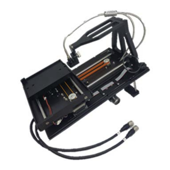
Figure 1 Microplate Reader and cover (P/N: N4201024)
PerkinElmer, 710 Bridgeport Avenue,
Shelton, CT 06484-4794, U.S.A
Produced in the USA.
Advertisement
Table of Contents

Related Manuals for Perkin-Elmer FL 6500


Summary of Contents for Perkin-Elmer FL 6500
- Page 1 09931528A FL 6500/ 8500 M icroplate R eader I nstallation I nstructions This instruction sheet describes the installation of this accessory which is used with the FL 6500/8500 Fluorescence Spectrometer. NOTE: Read these instructions before you install this accessory. Contacting P erkinElm er Supplies, replacement parts, and accessories can be ordered directly from PerkinElmer, using the part numbers.
-
Page 2: Dimensions And Specifications
09931528A Dim ensions and Specifications Physical Characteristic Specifications Microplate Reader Dimensions (mm) 218(W) x 340(D) x 290(H) Microplate Reader Weight (Kg) Microplate Reader Cover (mm) 259(W) x 430.5(D) x 331(H) Microplate Reader Cover Weight (Kg) 4.25 Available M icroplates Physical Characteristic Specifications The number of Wells Default: 96 or 384 and customize available... -
Page 3: Installation
• Figure 4 Cradles I nstallation 1. Prepare the FL 6500/8500 Fluorescence Spectrometer to install this accessory. 2. Connect the instrument power cord and the communication cable. 3. Loosen the accessory fixing bolt and remove the existing sample accessory. Figure 5 Loosening the accessory fixing bolt... - Page 4 4. Pull out the cell holder by hand. Figure 6 Pulling out the cell holder 5. Remove the existing front cover of the FL 6500/8500 using a screwdriver. Figure 7 Front Cover 6. Place the front cover of Microplate Reader and fasten the three bolts using a screwdriver.
- Page 5 8. Undo the four screws which attach the sample compartment lid to the FL 6500/8500. Figure 10 Remove the sample compartment lid 9. Tighten the four screws that secure the cover of the plate reader to the FL 6500/8500. Figure 11 Cover for the Microplate Reader 10.
- Page 6 09931528A 11. Fix the M4 bolts under the cradles using a 3 mm wrench. Figure 13 Fix the M4 bolts 12. Connect the M1 and M2 cables of the Microplate Reader into the accessory port. Figure 14 Connect M1 and M2 cables 13.
- Page 7 09931528A 14. Tighten the accessory fixing bolt. Figure 16 Accessory fixing bolt of Microplate Reader 15. Close the Microplate Reader cover and then, lock the latch at the left and right side of the front cover. Figure 17 Lock the latches NOTE: Sample loading can be done by opening the upper door of the Microplate Reader.
- Page 8 09931528A Calibration of M icroplate R eader 1. Execute the Spectrum FL software. → Microplate Reader icon 2. Select Options mode Or click the Accessory icon 3. The following window will appear. Select the plate you want to use. 4. Enter the required parameters on each tab if you know the whole plate information. List Function Select the type of well plate.
- Page 9 09931528A Row Count Enter the value for the number of rows. Enter the x and y distance of the A1 well to the upper right corner of Start X, Start Y the plate. Interval X, Enter the distance between the centers of two neighboring wells in Interval Y the x and y directions.
-
Page 10: M Anual Alignm Ent
09931528A M anual Alignm ent If you do not know the Plate information or A1 position is not correct, proceed the manual alignment. NOTE: 1. Prepare a micro plate and Scotch Magic Tape. Attach the magic tape onto the A1 and H12 ®... -
Page 11: Operation
09931528A 4. The following window appears. List Function Use these settings to define the distance the probe is moved Movement Setting head, each time an alignment arrow is pressed. Use 10 mm for the coarse tuning and 0.1 mm for the fine tuning. Use the arrows to align the probe. - Page 12 09931528A 7. Click Done in Step 2. 8. Align the beam to the centre of A1 using the Movement Control icons and click Done. 9. Align the beam to the centre of H12 using the Movement Control icons and click Done.
- Page 13 09931528A 10. Align the beam to the edge of H12 using the Movement Control icons and click Done. 11. Click Finish to save the plate information and close the window. 12. You can see that the Plate Information tab has been changed.
- Page 14 09931528A 13. Select any position in the micro plate picture and click Save and then Move to. Confirm that the beam is aligned well. 14. If the beam position is correct, Go to the following Measurement section. If the beam position is not correct, Execute the Manual Alignment again.
-
Page 15: Cycle Number
09931528A 4. When you click the Accessory of the Instrument Setting, the following window appears. a. When you select Center of Cell, the following setup window appears. List Function Selecting this means that whenever you click on a well to set a Center of Cell measurement point, the measurement point is automatically set to the center of the well. -
Page 16: Calculation Mode
09931528A List Function Selecting this means that whenever you click on a well to set a measurement point, the measurement point is set exactly where you clicked, rather than being automatically centered on the well. Normally the customize option is used for a large well (eg. 4 or 16) Customize Select Average or Sum. - Page 17 09931528A 6. Click the Position to select the cell position. 7. The following window will appear. Select the cell position using a mouse. NOTE: Each selection: Click the mouse, Each cancellation: Click the selected position again. Area selection: Drag the mouse, Area cancellation: Click the mouse outside the plate anywhere. 8.
- Page 18 09931528A...
Need help?
Do you have a question about the FL 6500 and is the answer not in the manual?
Questions and answers