
Subscribe to Our Youtube Channel
Related Manuals for Grundig SCC 3400 RDS


Summary of Contents for Grundig SCC 3400 RDS
- Page 1 CAR AUDIO SCC 3400 RDS DEUTSCH SCC 3460 RDS ENGLISH FRANÇAIS ITALIANO PORTUGUES ESPANOL NEDERLANDS...
- Page 2 Nur für Servicezwecke. Hinweis: Die Anschlüsse dürfen nicht beschaltet werden. Um die Lineausgänge mit Cinch-Kabeln zu verbinden wird der Line-Adapter 416 benötigt. Diesen erhalten Sie bei Ihrem Grundig CAR AUDIO Fach- händler! Additional connections ENGLISH Flat pin connectors C. CD changer/AUX connection:...
-
Page 3: Table Of Contents
Saving stations using the preset buttons Selecting preset stations Programme types (PTY) PTY function Assigning the PTY programme buttons Cassette (Tape) mode SCC 3400 RDS Selecting the TAPE input source Drive functions Cassette (Tape) mode SCC 3460 RDS Selecting the TAPE input source... - Page 4 The individual settings Coding Activating coding Deactivating coding Renewed operation Waiting times Fitting and removing the device Fitting the mounting frame and the device, connecting the antenna Fuse Power supply Loudspeakers Information Radio reception conditions Cleaning Troubleshooting Technical data GRUNDIG Service...
-
Page 5: Car Audio Scc 3400/3460 Rds
SCC 3460 RDS Operating manual The GRUNDIG environmental initiative GRUNDIG has used no plastics for the packaging of your device. The packaging consists entirely of cardboard or paper and can be disposed of for waste paper recycling. Special features of your device Your SCC 3400 or 3460 employs two anti-theft systems: coding and the detachable control unit. - Page 6 ________________ CAR AUDIO SCC 3400/3460 RDS Only you can switch the device on again by entering the code number. For instructions see the ”Coding” section starting on page Detaching and attaching the control unit In addition to coding you can also detach the control unit. This makes the device useless for thieves.
-
Page 7: Safety Instructions
SAFETY INSTRUCTIONS ______________________ Fitting the device We recommend that you have your device fitted by a specialist in order to guarantee trouble-free operation. Installation instructions can be found starting on page 29. Road safety Familiarise yourself with the various functions of the device before you use it while driving. -
Page 8: Overview
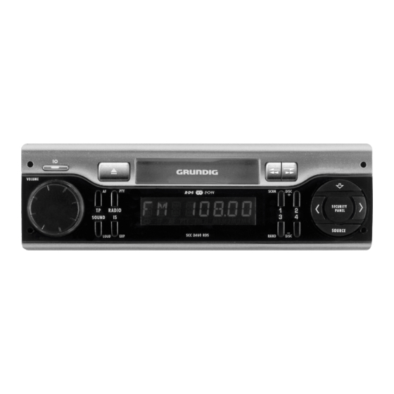
OVERVIEW ____________________________________________ Controls General On/off. Volume control knob. VOLUME Pressed briefly: FADER, BASS, TREBLE and SOUND/LOUD BALANCE sound settings. Pressed longer: Loudness function. Selects RADIO or CD as the input source. SOURCE Forward/back buttons. < > Unlocks the control unit. Radio mode Pressed briefly: RADIO input source, selects the RADIO/PTY... - Page 9 Pressed longer: Selecting alternative frequencies. Preset buttons for storing various programme 1, 2, 3, 4 types and stations. Cassette mode SCC 3400 RDS Changes the side of the tape. Fast forward and rewind. Ejects the tape. Cassette mode SCC 3460 RDS Changes the side of the tape.
-
Page 10: Display
___________________________ OVERVIEW Display ANTENNE TP AF PTY Display for input sources (RADIO, CD, AUX) and settings e.g. FM 2 FM band (1-3). e.g. FM 87 50 FM band, frequency. e.g. AM AM band. e.g. ANTENNE Station name. e.g. TAPE A/B Cassette function. -
Page 11: Basic Functions
BASIC FUNCTIONS ______________________________ Switching on and off To switch on and off press »IO«. Note: If the device is switched on while the ignition is on, it then switches off with the ignition and then on again, provided the contact is connected to terminal 15 of the vehicle (see page 29). - Page 12 __________________________________ BASIC FUNCTIONS Once you have selected the function you require, set the level using the »VOLUME« knob. BASS +0 9 – Display: Bass level raised by »+09«. To finish the setting keep pressing the »SOUND« button until RADIO N1 the selected station appears in the display.
-
Page 13: Radio (Tuner) Mode
RADIO (TUNER) MODE _______________________ Selecting the RADIO input source Press »IO« to switch on the device. EN ER GY – If the device was in RADIO mode when it was last switched off, you will hear the last station selected when you switch it on again. -
Page 14: Alternative Frequencies (Af)
______________________________ RADIO (TUNER) MODE To deactivate the TP function press the »TP« button once briefly. – Traffic news standby is deactivated. – »TP« disappears from the display. Additional TP functions To interrupt the current traffic news briefly press the »TP« button. -
Page 15: Intelligent Search (Is)
RADIO (TUNER) MODE ______________________________ There are three ways to search for stations: intelligent search (IS), RDS (Radio Data System) search and manual station search. Intelligent search (IS) The intelligent search first stores RDS (Radio Data System) stations, followed by the other stations in order of signal strength. When the IS search is completed up to 30 stations are stored. -
Page 16: Tuning To Rds Stations With Station Search
______________________________ RADIO (TUNER) MODE Tuning to RDS stations with station search Press »RADIO« to select the frequency band. FM 3 – Display: »FM 1«, »FM 2«, »FM 3« or »AM«. Note: To start a search in the FM band the IS function must be deactivated. -
Page 17: Saving Stations Using The Preset Buttons
RADIO (TUNER) MODE ______________________________ Briefly press »RADIO«. – The search function is deactivated. Note: After approximately 60 seconds the manual search ends automatically. Saving stations using the preset buttons The preset buttons »1«, »2«, »3«, »4« let you store four stations on each level of the FM band (1-3). -
Page 18: Programme Types (Pty)
______________________________ RADIO (TUNER) MODE Programme types (PTY) Many FM stations provide the Programme Type (PTY) service. During a news programme, for example, a station may broadcasts the NEWS identification code. The PTY function enables you to automatically tune to stations broadcasting a particular type of programme, for example POP. -
Page 19: Pty Function
RADIO (TUNER) MODE ______________________________ Searching for programme types There are two search methods for selecting a programme type. By default, the preset buttons »1«, »2«, »3« and »4« are assigned to four programme types: »1« NEWS, »2« SPORT, »3« POP and »4« CLASSICS. -
Page 20: Assigning The Pty Programme Buttons
______________________________ RADIO (TUNER) MODE Deactivating PTY Briefly press »PTY«. – Display: The »PTY« symbol disappears. – The PTY function is deactivated. Note: After approximately 10 seconds the PTY function ends auto- matically. Assigning the PTY programme buttons Although the preset buttons are delivered with four preset pro- gramme types, you can use them for other programme types: Press »PTY«... -
Page 21: Selecting The Tape Input Source
CASSETTE (TAPE) MODE ____________ With the SCC 3400 RDS Selecting the TAPE input source Insert a tape into the compartment. – Display: »TAPE A« or »TAPE B« TA PE A – or – In RADIO mode and with a tape already inserted: TA PE A Press »SOURCE«. -
Page 22: Drive Functions
CASSETTE (TAPE) MODE ____________ With the SCC 3460 RDS Selecting the TAPE input source Insert a tape into the compartment. – Display: »TAPE A« or »TAPE B« TA PE A - or - In RADIO mode and with a tape already inserted: TA PE A Press »SOURCE«. - Page 23 __________________ CASSETTE (TAPE) MODE Ending tape mode Briefly press »SOURCE« or »RADIO«. – The device switches to RADIO mode. – Display: e.g. »TAPE A« changes to »RADIO N1«. RADIO N1 Press and hold down » «. – The tape is ejected. Note: Before you switch off the device, always press »...
-
Page 24: Cd Mode With Cd Changer
CD MODE WITH CD CHANGER ________ Selecting the CD input source Briefly press »SOURCE«. DISC 01 Selecting a CD Keep pressing »DISC +« or »DISC -« until you see the number DISC 06 of the CD you want to hear in the display. CD playback functions Selecting and repeating tracks Press the »>«... -
Page 25: Errors In Cd Changer Mode
The CD changer is overheated. CD or DAT player connections If you are not using a GRUNDIG CD changer, you can also connect other CD or DAT (Digital Audio Tape) players to the car radio using a GRUNDIG CDP adapter, which is available as an accessory. -
Page 26: Expert Level
EXPERT LEVEL _______________________________________ To make the use of the device as simple as possible, a number of custom settings which are only required once or very occasionally are located on a special operating level (EXPERT). Optional EXPERT settings Code settings (»CODE/SAFE«). Display contrast (»DISPL 00«). -
Page 27: The Individual Settings
EXPERT LEVEL _________________________________________ The individual settings Code settings. See the detailed instructions starting on page 25. CODE – Coding is deactivated. – Coding is activated. SAFE Display contrast. DISPL 0 7 – Display: Scale »00« to »60«. Security LED on/off. –... - Page 28 _________________________________________ EXPERT LEVEL Switching on and off with ignition. – The car radio can be switched on and off with the vehicle ignition. – The device can only be switched on and off by pressing »IO«. OF F Note: In this case the contact (see page 30) must be connected to terminal 15 of the vehicle.
-
Page 29: Coding
CODING ________________________________________________ The code number for the device can be found on the identity card. Coding is not activated by default. If you activate coding, the device is electronically locked as soon as it is disconnected from the vehicle battery or the continuous positive terminal 30. It can only be switched on again if the code number is re-entered. -
Page 30: Renewed Operation
_______________________________________________ CODING Briefly press »EXP« to activate the setting. – Display: »1 - - - -« flashes. 1- --- Enter the code number using »<« and »>« or using the station buttons »1«, »2«, »3«, »4«. To confirm the setting, press »EXP« until »CODE« appears in the CODE display. -
Page 31: Waiting Times
CODING _______________________________________________ Waiting times In order to prevent unauthorised persons from switching on the radio and deactivating the coding by trial and error, waiting times are set between attempted code entries. During these times the device can be switched on and off, but it will not work. The device does not need to be switched on during the waiting time, but it does need to be connected to the permanent + 12 V supply. - Page 32 FITTING AND REMOVING _________________ Fitting the mounting frame and the device, connecting the antenna Ask your dealer for information on fitting equipment and other accessories. Fit the mounting frame in the radio recess of the vehicle (Fig. 1) (The illustrations are on page 31). Bend the catch flaps behind the radio recess inwards or out-...
-
Page 33: Fitting And Removing The Device
FITTING AND REMOVING THE DEVICE ___________ Power supply Flat pin connectors A (Fig. 4, page 31): Ground connection (minimum cross-section 2.5 mm positive and ground connection). Connect to terminal 31 (Ground) of the vehicle. +12 V operating voltage connection (minimum cross-section 2.5 mm for positive and ground connection). - Page 34 ___________ FITTING AND REMOVING THE DEVICE Loudspeakers Flat pin connector B (Fig. 4, page 31). Maximum output power at 4 Ω louspeakers: 4 x 20 W/4 x 40 W music signal power. Front loudspeakers Rear loudspeakers right + right + right - right - left +...
- Page 35 FITTING AND REMOVING THE DEVICE ___________ Fig. 1 Figs. 2/3 Fig. 4 13 16 19 15 18 17 20 T 10 A Fig. 5...
-
Page 36: Information
INFORMATION _____________________________________ Radio reception conditions Reception conditions in the VHF range change all the time during a journey. Mountains, buildings or bridges can impair reception. This is especially true when the station is very distant. Radio Data System (RDS) RDS is an information system for which most VHF stations transmit additional signals. -
Page 37: Troubleshooting
INFORMATION _______________________________________ Troubleshooting If a fault occurs, first refer to this information before you take the device for repair. If you are unable to rectify the fault using the information given here, contact your specialist dealer. Never under any circumstances attempt to repair the device yourself, as this invalidates the guarantee. -
Page 38: Technical Data
D-90471 Nürnberg D-13509 Berlin +49/40-7 33 31-0 +49/22 34-95 81-2 51 +49/6 21-33-76-70 +49/9 11-7 03-0 +49/30-4 38 03-21 GRUNDIG BELUX N.V. GRUNDIG SCHWEIZ AG GRUNDIG OY Deltapark, Weihoek 3, Unit Steinacker Straße 28 Luoteisrinne 5 CH-8302 Kloten SF-02271 Espoo... - Page 39 Grundig AG • Beuthener Str. 41 • D-90471 Nürnberg • http://www.grundig.com 18404-941.4100...
- Page 40 Nur für Servicezwecke. Hinweis: Die Anschlüsse dürfen nicht beschaltet werden. Um die Lineausgänge mit Cinch-Kabeln zu verbinden wird der Line-Adapter 416 benötigt. Diesen erhalten Sie bei Ihrem Grundig CAR AUDIO Fach- händler! Additional connections ENGLISH Flat pin connectors C. CD changer/AUX connection:...
Need help?
Do you have a question about the SCC 3400 RDS and is the answer not in the manual?
Questions and answers