Table of Contents
Advertisement
Service
Zusätzlich erforder-
Manual
liche Unterlagen
für den
Komplettservice:
SCD 5290 RDS
Additionally
required Service
Sach-Nr./Part No.
Manuals for the
72010-749.35
Complete Service:
SCD 5290 RDS
Änderungen vorbehalten
Subject to alteration
SERVICE MANUAL
Service
Manual
Sicherheit
Safety
Sach-Nr./Part No.
72010-800.00
H
P
1 B i t I n t e g r a l P r o c e s s i n g
I G H
O W E R
CHANGER CONTROL
(9.18304-8151 / G.HF 05-00)
Printed in Germany
VK 233 0496
SCD 5290 RDS
1 9 2 T i m e s O v e r s a m p l i n g
Service Manual Sach-Nr.
Service Manual Part No.
72010-749.35
Advertisement
Table of Contents

Related Manuals for Grundig scd 5290 rds


Summary of Contents for Grundig scd 5290 rds
- Page 1 SERVICE MANUAL Service Service Zusätzlich erforder- Manual Manual liche Unterlagen für den Sicherheit Komplettservice: SCD 5290 RDS Safety Additionally required Service Sach-Nr./Part No. Sach-Nr./Part No. Manuals for the 72010-749.35 72010-800.00 Complete Service: SCD 5290 RDS 1 B i t I n t e g r a l P r o c e s s i n g...
-
Page 2: Table Of Contents
AF Voltmeter Stereocoder Stereo Coder Wobbler Sweep Generator Beachten Sie bitte das GRUNDIG Meßtechnik-Programm, das Sie Please note the Grundig Catalog “Test and Measuring Equipment” unter folgender Adresse erhalten: obtainable from: GRUNDIG electronics GmbH GRUNDIG electronics GmbH Würzburger Str. 150 Würzburger Str. -
Page 3: Ausbauhinweise
SCD 5290 RDS Allgemeiner Teil / General Section Ausbauhinweise Disassembly Instructions 1. Öffnen des Gehäuses (Fig. 1) 1. Opening the Cover (Fig. 1) - Die 2 Schrauben A herausschrauben. - Undo the 2 screws A. - Den Deckel mit einem Schraubendreher an den Punkten B an- - Lift the cover with a screwdriver at the points B and remove it. - Page 4 Allgemeiner Teil / General Section SCD 5290 RDS 4. Ausbau der Frontblende 4. Removing the Front Panel - Die 2 Flexprintstecker G und H (Fig. 5) öffnen. - Disconnect the 2 flexprint connectors G and H (Fig. 5). - Das Bedienteil abnehmen und die 2 Schrauben J (Fig. 6) heraus- - Remove the operating part and undo the 2 screws J (Fig.
-
Page 5: Bedienhinweise
“ -Taste drücken. fach wie möglich ist, befinden sich eine Viel- das Bedienteil noch einmal ab und setzen Sie GRUNDIG Umwelt-Initiative zahl von Einstellungen, die Sie nur einmal es erneut ein. Bleibt der Zünd-/Anlaßschalter ausgeschaltet, oder nur gelegentlich brauchen, in einer... - Page 6 Verstärker Verstärker Einstellung beenden: Einstellungen aufrufen Ein- und Ausschalten am Autoradio Bässe BASS Höhen TREB (Treble) Lautstärkeverhältnis FAD (Fader) ¡ ¡ Drücken Sie die -Taste und danach kurz -Taste so oft drücken, bis die normale S OUND S OUND “ ¡...
- Page 7 Radio Radio AF-Funktion ausschalten. Momentane Verkehrsfunk-Durchsage CULTURE Kultur, Kirche und Gesellschaft – “ Speicherplatz-Tasten “ Alternative Frequenzen (AF) Durchsagebereitschaft für Verkehrs- abbrechen: Wenn Sie sich in einem sehr schlecht ver- funk-Durchsagen (TP) SCIENCE Wissenschaft Im Display: »AF« sorgten Empfangsgebiet aufhalten, kann es ¡...
- Page 8 Compact Disc (CD) mit »GRUNDIG CD-Wechsler«* Compact Disc (CD) mit »GRUNDIG CD-Wechsler« Externer CD- oder DAT-Betrieb Programmquelle CD-Wechsler wählen Titel wählen bzw. wiederholen Titel der CD in zufälliger Reihenfolge CD`s in zufälliger Reihenfolge CD-Betrieb beenden CD- oder DAT-Spieler anschließen (TRACK RANDOM) (CD RANDOM) “...
- Page 9 Wissenswertes Codierung Codierung Geschwindigkeitsabhängige Lautstärke Hinweise zur Codierung Codierung aktivieren Wartezeiten Wiederinbetriebnahme Codierung deaktivieren SCV = Speed Controlled Volume Die Code-Nummer Ihres Autoradios befindet 1. Expert-Mode ist eingeschaltet und Damit das Deaktivieren der Codierung nicht War das Autoradio von der Autobatterie (bzw. z.B.
-
Page 10: Operating Hints
If it should not be possible to switch the radio vehicle: To make car radio operation as easy as possi- “ on with the button, remove and refit the GRUNDIG environment initiative “ Press the button. ble, numerous settings that you need only control panel. - Page 11 Amplifier Amplifier Terminate the setting: Calling up settings Switching on and off on the car radio BASS TRE (Treble) FAD (Fader) ¡ ¡ Press the button and then, Repeatedly press the button until the S OUND S OUND “ ¡ ¡...
- Page 12 Radio Radio Switching off the AF function To abort a traffic announcement CULTURE Culture, church and society – “ Memory position buttons “ Alternative frequencies (AF) Traffic announcement standby (TP) ¡ When you are in an area with very poor recep- briefly press the TP/AF button.
- Page 13 í signal sounds: sounds: display indicates "MC01". If you have not connected a GRUNDIG CD “ (TRACK + ) button: go to next track. "TR RND" appears briefly in the display. "CD RND" appears briefly in the display. changer, you can also connect other CD “...
- Page 14 Important Information Coding Coding Speed controlled volume Information about coding Activating coding Waiting periods Return to operation Deactivating coding Your personal code number is on the identity 1. The expert mode is switched on and To prevent deactivation of the coding being The car radio is electronically disabled after it e.g., before removing the car radio: SCV = Speed Controlled Volume...
-
Page 15: Allgemeiner Teil
SCD 5290 RDS Allgemeiner Teil / General Section Notizen / Notes GRUNDIG Service 1 - 15... -
Page 16: Dc-Voltmeter
Abgleichvorschriften / Adjustment Procedures SCD 5290 RDS Abgleichvorschriften 1. Hauptplatte Meßgeräte: DC-Voltmeter, Meßsender, NF-Voltmeter, Stereocoder, Wobbler Abgleich Vorbereitung Abgleichvorgang ± 1. MW-Oszillator Mit L 612A (1) bei 531kHz auf 1,2V 50mV abgleichen. ± DC-Voltmeter an FMP 639. Kontrolle bei 1602kHz auf 7,5V 0,5V. -
Page 17: Adjustment Procedures
SCD 5290 RDS Abgleichvorschriften / Adjustment Procedures Adjustment Procedures 1. Electrical Adjustment Test equipment: DC Voltmeter, Test Generator, AF Voltmeter, Stereo Coder, Sweep Generator Adjustment Preparation Adjustment Procedure ± 1. MW Oscillator Align with L 612A (1) at 531kHz to 1.2V 50mV. - Page 18 Abgleichvorschriften / Adjustment Procedures SCD 5290 RDS Abgleichlageplan Alignment Layout CR104 F105 T2002 IC1471L CR204 F101 C607A F601A L604A IC2001 L603A BU1102V BU1101U C606A L612A L613A BU2002 BU1021 Q2651C BU2003 BU1022 19373-382.50 (01)/4B S1020L L2300 S1023L S1021L L2306 S1022 L2301...
-
Page 19: Bauteilhinweise
SCD 5290 RDS Schaltpläne und Druckplattenabbildungen / Circuit Diagrams and Layout of PCBs SCD 5290 RDS Schaltpläne und Druckplattenabbildungen / Circuit Diagrams and Layout of PCBs Schaltpläne und Druckplattenabbildungen / Circuit Diagrams and Layout of PCBs Bauteilhinweise / Notes on Components... - Page 20 Schaltpläne und Druckplattenabbildungen / Circuit Diagrams and Layout of PCBs SCD 5290 RDS Schaltpläne und Druckplattenabbildungen / Circuit Diagrams and Layout of PCBs SCD 5290 RDS HF-Teil / RF Part FM-OSZILLATOR FM-VORSTUFE CT126 DRAHTBRUECKE ZUR CR126 FM PRE STAGE FM-ZF-TEIL...
- Page 21 SCD 5290 RDS Schaltpläne und Druckplattenabbildungen / Circuit Diagrams and Layout of PCBs SCD 5290 RDS Schaltpläne und Druckplattenabbildungen / Circuit Diagrams and Layout of PCBs CR205 CR201 VOLLELEKTR. STOERAUSTASTUNG UND STEREODECODER FULLY ELEC.INTERFER. SUPPR. CIRCUIT AND STEREO DECODER CR202...
-
Page 22: Prozessor-Teil
Schaltpläne und Druckplattenabbildungen / Circuit Diagrams and Layout of PCBs SCD 5290 RDS Schaltpläne und Druckplattenabbildungen / Circuit Diagrams and Layout of PCBs SCD 5290 RDS Prozessor-Teil / Processor Part CR860 CR810 CL801 CR850 FMP801 CR879 10UH CR876 CR877 CR878... - Page 23 SCD 5290 RDS Schaltpläne und Druckplattenabbildungen / Circuit Diagrams and Layout of PCBs SCD 5290 RDS Schaltpläne und Druckplattenabbildungen / Circuit Diagrams and Layout of PCBs VLCD RDS-DECODER LCD UND TREIBER 19720-250.00 LCD AND DRIVER TREIBER PCF 8576 FMP2301 R2301...
-
Page 24: Cd-Teil
Schaltpläne und Druckplattenabbildungen / Circuit Diagrams and Layout of PCBs SCD 5290 RDS Schaltpläne und Druckplattenabbildungen / Circuit Diagrams and Layout of PCBs SCD 5290 RDS CD-Teil / CD Part Bedienplatte / Operating Board CD-LAUFWERK SONY CMX-205 SACHNUMMER: 19723-023.00 CR1052... - Page 25 SCD 5290 RDS Schaltpläne und Druckplattenabbildungen / Circuit Diagrams and Layout of PCBs SCD 5290 RDS Schaltpläne und Druckplattenabbildungen / Circuit Diagrams and Layout of PCBs Anschlußplatte / Connecting Board II-5 II-5 II-6 II-6 II-8 II-8 II-7 II-7 II-3 II-3...
- Page 26 Schaltpläne und Druckplattenabbildungen / Circuit Diagrams and Layout of PCBs SCD 5290 RDS Schaltpläne und Druckplattenabbildungen / Circuit Diagrams and Layout of PCBs SCD 5290 RDS NF-Teil / AF Part ENDSTUFEN DIGITALER KLANGSTELLER POWER AMPLIFIER DIGITAL TONE CONTROL MODE DIAG SUPPLY SEL.
- Page 27 SCD 5290 RDS Schaltpläne und Druckplattenabbildungen / Circuit Diagrams and Layout of PCBs SCD 5290 RDS Schaltpläne und Druckplattenabbildungen / Circuit Diagrams and Layout of PCBs FMP1643 PPLY FMP1642 C1601 SVRR FMP1641 N.C. ANSCHLUSSPLATTE DA8561Q 19373-094.00 FMP1640 CONNECTING BOARD TRATE) R.GND...
- Page 28 Schaltpläne und Druckplattenabbildungen / Circuit Diagrams and Layout of PCBs SCD 5290 RDS Schaltpläne und Druckplattenabbildungen / Circuit Diagrams and Layout of PCBs SCD 5290 RDS Hauptplatte blau Lötseite Koordinaten der Bauteile blue Solder Side Coordinates of Components Bauteile der Bestückungsseite, Sicht auf Bestückungsseite Pos.-Nr./...
- Page 29 SCD 5290 RDS Schaltpläne und Druckplattenabbildungen / Circuit Diagrams and Layout of PCBs SCD 5290 RDS Schaltpläne und Druckplattenabbildungen / Circuit Diagrams and Layout of PCBs Bauteile der Bestückungsseite, Sicht auf Lötseite blau Lötseite Koordinaten der Bauteile Components of Component Side, View on Solder Side...
- Page 30 Schaltpläne und Druckplattenabbildungen / Circuit Diagrams and Layout of PCBs SCD 5290 RDS Schaltpläne und Druckplattenabbildungen / Circuit Diagrams and Layout of PCBs SCD 5290 RDS SMD-Bauteile der Bestückungsseite, Sicht auf Bestückungsseite blau Lötseite Koordinaten der Bauteile SMD Components of Component Side, View on Component Side...
- Page 31 SCD 5290 RDS Schaltpläne und Druckplattenabbildungen / Circuit Diagrams and Layout of PCBs SCD 5290 RDS Schaltpläne und Druckplattenabbildungen / Circuit Diagrams and Layout of PCBs SMD-Bauteile der Lötseite, Sicht auf Lötseite blau Lötseite Koordinaten der Bauteile SMD Components of Solder Side, View on Solder Side...
-
Page 32: Bedienplatte
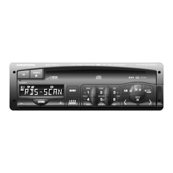
Schaltpläne und Druckplattenabbildungen / Circuit Diagrams and Layout of PCBs SCD 5290 RDS Schaltpläne und Druckplattenabbildungen / Circuit Diagrams and Layout of PCBs Ersatzteillisten und Explosionszeichnungen / Spare Parts List and Exploded Views SCD 5290 RDS SCD 5290 RDS Anschlußplatte / Connecting Board Sicht auf Lötseite... - Page 34 E O N CHANGER CONTROL SECURITY NEWS SPORT LEARN ROCK CLASSICS PERS...
Need help?
Do you have a question about the scd 5290 rds and is the answer not in the manual?
Questions and answers