Table of Contents
Advertisement
Advertisement
Table of Contents

Related Manuals for CellarCool CM Series

Summary of Contents for CellarCool CM Series
- Page 1 NOTICE: To activate the split system warranty, the installing certified HVAC/R service tech must complete the split system warranty checklist and send back to CellarCool. Tech Support: 1 (800) 343-9463, ext. 801 Hours: Monday through Friday, 7 AM - 4 PM...
- Page 2 CellarCool. Every effort has been made to ensure that the information in this manual is accurate. CellarCool is not responsible for printing or clerical errors.
-
Page 3: Table Of Contents
Controller Functions ..........41 CellarCool Troubleshooting Guide ....... . 47 Maintenance Schedule . - Page 4 WARNING The evaporator unit (fan coil unit) must be insulated using the insulation blanket provided in accordance with this manual. Refer to the insulation blanket installation instructions. Failure to follow the instructions provided will result in a poor vapor barrier, water damage, rust, and system corrosion which will void the warranty on your unit.
-
Page 5: Introduction
INTRODUCTION Customer Service Thank you for purchasing a CellarCool cooling system. We strive to provide the highest-quality products and the best possible customer service. If you have any questions about your system, please call us at 1-800-343-9463 or visit cellarcool.com. -
Page 6: Quick Start Guide
CellarCool units utilize a solenoid valve on the liquid line and a low-pressure switch on the suction line. When the thermostat calls for cooling, the solenoid valve opens, permitting the flow of refrigerant. The low-pressure switch then signals the compressor to cycle on. -
Page 7: Before You Start
7. CellarCool requires that all split systems be installed by a certified HVAC-R technician only. NATE or equivalent is recommended. If you encounter a problem with your CellarCool system, please refer to the Troubleshooting Guide. If you have any further questions or concerns, or need technical assistance, please contact CellarCool’s Customer Service at 1-800-343-9463. -
Page 8: Receiving & Inspecting The System
Allow the condensing unit to sit for 24 hours prior to start-up. The condensing unit can be placed in the installation location, piped and evacuated during this time. Note: CellarCool units are manufactured in the USA and tested prior to shipment. •... -
Page 9: Quick Reference Guide
Supply and Return Grille (Paintable) Mounting Bracket (Paintable) Top View Line Set Knockout Top Panel Options Electrical Knockout Options Note: The unit comes in black. The mounting bracket and front grille are paintable, enabling you to match your desired color. www.cellarcool.com | Page 7... -
Page 10: Knockout Locations
KNOCKOUT LOCATIONS KNOCKOUT LOCATIONS 20.4” 15.35” 1.5” Top View of Evaporator Unit 14.1” 8.05” 34.25” 1.75” 35.75” 20.4” 15.35” 4.57” Side View of Evaporator Unit 1.5” 12.65” 12.65” 6.58” 1.75” 35.75” 14.10” 12.65” PROPRIETARY AND CONFIDENTIAL NEXT ASSY 2” 4.58” 1.45”... - Page 11 Thermostat Advanced digital display (50-ft. cable), liquid-temperature-measuring bottle probe (50-ft. cable) Temp. Delta Can maintain a 55°F cellar temperature with up to 110°F condenser air intake temperature Warranty Two-year limited warranty (parts and labor) www.cellarcool.com | Page 9...
- Page 12 CM5000 SPECIFICATIONS 5000 Evaporator 5000 Condenser Model (Fan Coil Unit) (Air-Cooled Condensing Unit) Cellar Size Approx. 2000 cu. ft. when cellar is fully insulated and sealed with a proper vapor barrier* BTU/h w/85°F air entering 5245 condenser coil Dimensions 35.75”L x 14.5”W x 12.75”H 16.08”...
- Page 13 NOTE: Cool temp may indicate liquid in the compressor. Voltage and Amp Draw A. Measure voltage to compressor and amp draw. Condensation Drain Test A. Pour water into the drain pan to assure it drains properly. www.cellarcool.com | Page 11...
-
Page 14: Items To Route Before Installing The Evaporator Unit
ITEMS TO ROUTE BEFORE INSTALLING THE EVAPORATOR UNIT Routing Instructions: Route the line set from the condensing unit to the desired evaporator unit installation location. Route the display cable from the desired location to the evaporator installation location (see page 22 for more controller information). -
Page 15: Selecting Mounting Option
Mounting options are listed below: Flush mount option 12.65” Partially recessed mounting option 6.9” 5.75” Choose a mounting option suitable for the installation location. 5.75” 6.9” Fully exposed mounting option 12.65” www.cellarcool.com | Page 13... -
Page 16: Mounting The Evaporator Unit
MOUNTING THE EVAPORATOR UNIT NOTE: If installing the unit without attic access, perform steps 5-23 prior to steps 3-4. Secure the mounting bracket to the unit using the twelve (12) supplied 3/8” Phillips pan-head screws. NOTE: You are REQUIRED to use only the mounting locations provided. These locations ensure that the installer will not drill into any copper or electrical wiring within the system. -
Page 17: Evaporator Unit Preparation
5-8 after the unit has been mounted. Locate the white zip tie securing the drain line tube to the suction line and cut it. Direct the end of the drain line away from refrigerant lines. CUT THIS ZIP TIE DO NOT CUT www.cellarcool.com | Page 15... -
Page 18: Installing The Evaporator Unit
INSTALLING THE EVAPORATOR UNIT Remove the protective caps from the liquid and suction line connection tubes. Using copper tubing per line set sizing chart, route the liquid and suction lines to the tubing coming from the unit. Place a wet rag around the suction and liquid lines approximately 4” from the braze joints. This will prevent excess heat from damaging components. - Page 19 Install the supplied three-inch pieces of cork tape around the display cable, bottle probe cable, and power wires. NOTE: The unit comes in black. The mounting bracket and front grille are paintable, enabling you to match your desired color. www.cellarcool.com | Page 17...
-
Page 20: Insulation Blanket Installation
INSULATION BLANKET INSTALLATION *Tools required: spray adhesive, utility knife, cork tape, foil tape CM2500 blanket dimensions 68” 22” Insulation Blanket Insulation Blanket 11.25” 11” CM3500/5000 blanket dimensions 102” 35.75” Insulation Blanket Insulation Blanket 14.25” 14.25” 1. Once mounting bracket location has been selected and installed, proceed to the insulation blanket installation. 2. - Page 21 4. Once insulation is installed, apply foil tape to all seams, covering them completely. 5. Inspect insulation for damage/defects. If damaged, repair with foil tape. 6. Apply cork tape or equivalent to areas where the line set, wiring, and drain line enter the unit. www.cellarcool.com | Page 19...
-
Page 22: Drain Line
Drain Line The CM Series evaporator unit features a drain line pump system that removes excessive condensate build up in the drain pan. During operation, the drain pan collects water that drips from the coil. The drain line pump system will prevent overflow and leaking by allowing for discharge of the additional condensate. -
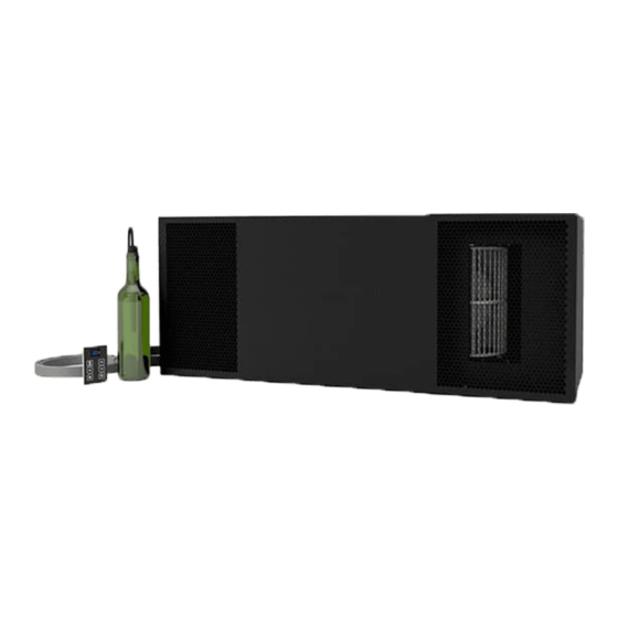
Page 23: Liquid-Measuring Thermostat (Bottle Probe)
CM SERIES LIQUID-MEASURING THERMOSTAT SYSTEM (BOTTLE PROBE) CellarCool cooling units come with a liquid-temperature-measuring thermostat. The self-calibrating probe contains a sensor chip, which communicates back and forth with the thermostat. This results in a consistent temperature setting and accuracy. Wine should be kept at a very precise, controlled temperature and humidity. By measuring the liquid temperature rather than air, the unit will operate 75–80% of the time. - Page 24 REMOTE DISPLAY: INSTALLATION AND CONFIGURATION* Tools needed: 5/16” drill bit, 3/16” drill bit, drywall saw, level, pencil What’s included: Display panel, wall mount bracket, flush mount bracket, flush mount template °F Display panel Wall mount bracket Flush mount bracket Flush mount template WALL MOUNT BRACKET INSTALLATION 1.
- Page 25 3. Place bracket against wall, aligning screw holes with drywall anchors. Insert the four supplied Phillips-head screws into the drywall anchors. Tighten the screws to secure the bracket to the wall. www.cellarcool.com | Page 23...
- Page 26 WALL MOUNT BRACKET INSTALLATION, CONTINUED NOTE: Before you continue to Step 4, locate the area where the display will be mounted. You may route the display wire into the housing one of three ways: either through the wall or through one of the holes on the top or bottom edges of the wall mount bracket.
- Page 27 2. Place the external drip tray on a level surface. Place a vibration isolator on each end of three of the drip tray risers. The vibration isolator needs to be pushed up against the outer lip on the top of the risers. Each vibration isolator should be spaced about 17.5” apart. Center the evaporator unit on the vibration isolators. www.cellarcool.com | Page 25...
- Page 28 FLUSH MOUNT BRACKET INSTALLATION, CONTINUED 5. Remove the backing from the double-sided tape on the flush mount bracket. 6. Align magnets with previously drilled holes. Make sure the cut-out portion of the bracket (circled below) is on the bottom. Press the bracket firmly against the wall. WALL HOLE CUTOUT...
- Page 29 8. Place the display on the flush mount bracket as shown, attaching the back of the display panel to the magnets on the mounting bracket. Make sure that the alignment tab on the back of the display panel sits in the notch on the bot- tom of the bracket. WALL www.cellarcool.com | Page 27...
- Page 30 CM SERIES WIRING DIAGRAM ELIWELL RTN400 KDT PLUS DISPLAY Pb3 CPB KEYB NEUTRAL LINE OUT 2 OUT 3 OUT 4 NEUTRAL LINE OUT 1 WHITE BLACK BLACK BLACK BLACK BLACK RESERVOIR CONDENSATE PUMP BLUE BLACK 115V LINE WHITE 115V NEUTRAL...
-
Page 31: Cm 3500/5000 Condensing Unit
CM SERIES CM3500/5000 CONDENSING UNIT WIRING DIAGRAM www.cellarcool.com | Page 29... - Page 32 COPELAND COLD WEATHER START KIT WIRING DIAGRAM For systems manufactured after October 31, 2018 Black Black COPELAND CWSK HEATER Page 30 | 1-855-235-5271 081619...
-
Page 33: Preparing The Condensing Unit
Provide a weatherproof disconnect for the condensing unit if it is located outside. Power surges and spikes can damage sensitive electrical equipment. CellarCool recommends plugging the unit into a surge protector or power conditioner in order to protect your system. As outlined in our terms and conditions, power surges and spikes are not covered under warranty. - Page 34 PREPARING THE CONDENSING UNIT (continued) The condensing unit can be installed inside a well-ventilated area of the home, but is typically installed outside. Exterior applications will require the use of a protective housing. The amount of sun exposure should be considered when selecting the placement of the condensing unit .The 3500 condensing unit requires a dedicated 15-amp circuit (non-GFI).
-
Page 35: Installing The Condensing Unit
3. Leave the circuit breaker off until the unit is ready to charge. Note: Do not apply power to a system without refrigerant. Copeland Wiring Procedure Step # Use a ¼” nut driver to remove the screw securing the cover to the compressor electrical compartment. www.cellarcool.com | Page 33... - Page 36 Copeland Wiring Procedure Step # Remove the cover to expose the internal wires. Copeland Wiring Procedure Step # Route the required 115V power wires into the open clamp on the enclosure. Page 34 | 1-855-235-5271 081619...
- Page 37 Perform the following wire connections: • Insert the Line 115V wire into the “H” lever connector • Insert the Neutral 115V wire into the “N” lever connector • Insert the Ground wire into the “G” lever connector www.cellarcool.com | Page 35...
- Page 38 Copeland Wiring Procedure Step # Push wires back into enclosure. Copeland Wiring Procedure Step # Re-install cover. Page 36 | 1-855-235-5271 081619...
-
Page 39: Line Set Piping Diagrams
It is required to size the suction line tubing according to this chart. Line Set Length <25ft 26-50ft 50-100ft CM3500/5000 Vertical Rise 15ft <3ft 3-10ft >10ft <3ft 3-10ft >10ft Horizontal Tubing 1/2” 5/8” Suction Line Vertical Rise 1/2” 1/2” Horizontal Tubing 1/4” Liquid Line Vertical Rise 1/4” www.cellarcool.com | Page 37... - Page 40 DO NOT BLOCK airflow through the INSTALLING THE CONDENSING UNIT exterior housing. This will restrict airflow and void the warranty. Refrigerant Piping Overview • Using the charts and illustrations found above, route the line set between the evaporator unit and condensing unit. Be sure to reference the chart for correct line set sizing.
- Page 41 • Confirm that the control is displaying the correct temperature and that no alarms are present. Refer to page 43 for corrective action if alarms are present. FINALIZING THE INSTALLATION Push the grille back into place. This will attach the grille to the ball studs. Screw in the eight screws to secure the front access panel. www.cellarcool.com | Page 39...
-
Page 42: System Operation
SYSTEM OPERATION Initial Start-Up Operation in Low Ambient Temperatures When the unit is plugged in and power is sent to the The condensing unit comes equipped with a LAC (Low controller, a beep will sound, confirming that the controller is Ambient Control). - Page 43 Fan is on Anti-Frost Cycle running °F Scroll Button Return to Previous Menu Change Setpoint View/Change Setpoint Scroll Button Enter User Menu Change Setpoint (hold for 3 sec) Unlock Button Power On/Off (hold for 1 sec) www.cellarcool.com | Page 41...
-
Page 44: Controller Functions
CONTROLLER FUNCTIONS Button Normal Functions °F INITIAL STARTUP When the unit is plugged in and power is sent to the controller, a beep will sound, confirming that the controller is getting power. All LEDs on the display will blink three times. Three dashes will then appear on the screen. - Page 45 The alarm icon is shown when the unit encounters an issue that needs attention. Alarm codes are explained on the following page. All temperature-related alarms are blocked for the first 10 hours after the unit is plugged in to allow the system to stabilize and acclimate to the new environment. www.cellarcool.com | Page 43...
- Page 46 CELLARCOOL CONTROLLER ALARM CODES Code Cause Solution The following alarm codes will be displayed on the screen along with the alarm icon. Bottle probe is not connected Attach bottle probe to circular connector Faulty bottle probe connection Locate faulty bottle probe connection by inspecting all wiring connections between the bottle probe and the circuit board.
- Page 47 2. 2 = activates the compressor and fans 5 = disables the compressor and fans NOTE: Setting the dOA to any number other than 2 or 5 will prevent the unit from operating properly. www.cellarcool.com | Page 45...
- Page 48 Emerson Electronic Unit Controller ™ Quick setup and troubleshooting guide Fan light 1 & 2 Compressor Adjusting Low Pressure Settings Book of Alarms – (Fan cycle units only) to enter alarm menu Hold DOWN and SET simultaneously for 3 seconds to enter menu (PSI light will ...
- Page 49 Hp switch resets), and any minimum off time will need to complete (5 minutes for the xed Hp switch) EmersonClimate.com/ElectronicUnitController 2013ECT-46 (9/13) Emerson is a trademark of Emerson Electric Co. ©2013 Emerson Climate Technologies, Inc. All rights reserved. www.cellarcool.com | Page 47...
-
Page 50: Cellarcool Troubleshooting Guide
CELLARCOOL TROUBLESHOOTING GUIDE Unit has ice forming on the evaporator unit Possible cause Solution Evaporator filter or coil is dirty Remove the filter and wash it, then clean the coil with a vacuum. If coil is very dirty, use a spray bottle with a small amount of liquid dish detergent or coil cleaner. - Page 51 Please contact the installing technician to troubleshoot Compressor and /or starting components faulty Please contact the installing technician to troubleshoot Humidity in cellar too low Possible cause Solution Not enough moisture Purchase and place a humidifier (or a decorative fountain) in cellar www.cellarcool.com | Page 49...
-
Page 52: Maintenance Schedule
MAINTENANCE SCHEDULE Monthly 1. Check coils 2. Check for unusual noise or vibration 3. Check the drain line to see if it is above the waterline (if draining into a vessel) Quarterly 1. Use a vacuum with brush attachment to clean coils; be careful not to crush coil fins when cleaning 2. - Page 53 This can lead to a high concentration of the include proper clothing, gloves and eye protection. agent and possible corrosion of the tubing and/or base. www.cellarcool.com | Page 51...
-
Page 54: Bypass Test Procedure
BYPASS TEST PROCEDURE NOTE: If instructed by a CellarCool representative, follow the directions below to test the cooling unit using the bypass plug provided in the accessory kit. 1. Disconnect power from the evaporator unit. 2. Loosen the two (2) screws on the front of the grille or duct plenum. -
Page 55: Technical Assistance
TECHNICAL ASSISTANCE CellarCool Customer Service is available Monday through Friday from 6:00 a.m. to 4:00 p.m. Pacific Standard Time. The appointed customer service representative will be able to assist you with your questions and warranty information more effectively if you provide them with the following: •... - Page 56 CellarCool warrants against defects in material and workmanship as follows: 1. LABOR - For a period of two (2) years commencing on the date of purchase, CellarCool will, at its option and discretion, reimburse up to $250 to the End User for cost incurred for servicing, repairing, removing or installing warranty parts.
- Page 57 8. This limited warranty is voided if installed in an enclosure of insufficient design that does not follow the Product installation requirements stated herein and in the owner’s manual. 9. Removing the rivets from the Product’s unit housing without prior authorization from CellarCool voids this limited warranty.
- Page 58 E. End User is responsible for all costs incurred for the installation and/or removal of the Product, or any part thereof, unless such cost has been agreed by CellarCool to be a warranty repair prior to the work being performed.
- Page 59 Conditions of Sale shall be interpreted as through drafted jointly by CellarCool and Purchaser. Any dispute will be resolved by the courts in and for the County of San Joaquin, State of California, and all parties, CellarCool, Purchaser and End User, hereby irrevocably submit to the personal jurisdiction of such courts for that purpose.
- Page 60 Web: www.cellarcool.com B. Technical Assistance. CellarCool Customer Service is available Monday through Friday from 6:30 a.m. to 4:00 p.m. PST. The Customer Service representative will be able to assist you with your questions and warranty information more effectively if you provide them with the following: 1.
- Page 61 CellarCool 1738 E. Alpine Ave Stockton, CA 95205 1(800) 343-9463 www.cellarcool.com...
Need help?
Do you have a question about the CM Series and is the answer not in the manual?
Questions and answers