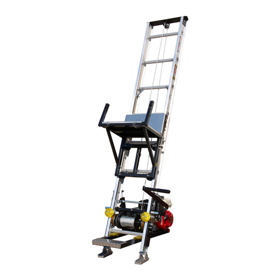
TRANZSPORTER TP250 Owner's Manual
Platform hoist
Hide thumbs
Also See for TP250:
- Owner's manual (16 pages) ,
- Assembly instructions manual (8 pages) ,
- Assembly manual (4 pages)
Table of Contents
Advertisement
Quick Links
CRITICAL SAFETY INFORMATION: The greatest exposure to serious bodily injury and or death may occur when the
Tranzsporter track sections are located within 10 ft. (left or right or underneath) overhead electric power lines. If a minimum
safe distance (10 ft.) from electrical wires cannot be maintained, contact the local utility company and have the electric wire
unenergized and grounded or guarded effectively by insulating or other means.
A COMPETENT PERSON must be present during any set up, during any repositioning, and during any tear down operations
of the Transporter track sections when the Transporter is to be located near electric power lines. A COMPETENT PERSON must
read and understand the Owners Manual for set up, operating instructions, and tear down instructions in order to insure that
all personnel authorized to set up, operate, and tear down the Transporter are made aware of ALL SAFETY WARNINGS as well
as the operating instructions. ALWAYS USE APPROVED ROOF TOP fall protection when setting up, operating, and taking down
the Tranzsporter Hoist.
Instructions #08238 Rev. 4/8/19
Platform Hoist
Color Logo use on white background only
Red: 0-100-100-0
Owners Manual
Black Logo use on white background only
For the Most Up to Date Information and
Instructions, Visit the TranzSporter Web Site
White Logo use on black background only
Blue: PMS 293
100-56-0-0
Updated: 4/8/19
TP250
250 lb. Capacity
TP400
400 lb. Capacity
at www.tranzsporter.com.
E1399
Advertisement
Table of Contents

Subscribe to Our Youtube Channel
Related Manuals for TRANZSPORTER TP250


Summary of Contents for TRANZSPORTER TP250
- Page 1 White Logo use on black background only Tranzsporter track sections are located within 10 ft. (left or right or underneath) overhead electric power lines. If a minimum safe distance (10 ft.) from electrical wires cannot be maintained, contact the local utility company and have the electric wire unenergized and grounded or guarded effectively by insulating or other means.
- Page 2 • Amber colored carriage bumpers to protect against damage and wear from repeated lowering (can be rotated). • Oversized clip pins for fast and simple removal of quick change cable drum and belt replacement. Your new Tranzsporter Lift Hoist is shipped in 3 boxes and one track section bundle Base Section Carriage Base Engine/Motor Base Includes: 4ft.
- Page 3 General Safety Instructions: In order to set up and operate the Tranzsporter ladder hoist safely in and around ELECTRIC POWER LINES and be compliant with OSHA Regulations 1926.416(a) , the following must be ascertained prior to setting up the Tranzsporter each time for the Protection of Employees .
- Page 4 6. DO NOT ALLOW ANYONE TO OPERATE THE TRANZSPORTER HOIST WHO HAS NOT BEEN THOROUGHLY AND PROPERLY TRAINED IN THE CORRECT OPERATION AND USE OF THIS HOIST. 7. This hoist is manufactured to lift materials only. Do not use the TranzSporter Hoist for the purpose of transporting personnel from one level to another.
- Page 5 General Safety Instructions (Continued): 13. Store all parts of the TranzSporter Hoist in such a fashion as not to damage any of the components. 14. Do not operate indoors or in an area with poor ventilation. Electric motor model is excluded.
- Page 6 Assembly Instructions for the TP250 Hoist Instructions for the TP400 Hoist skip to page 8 Step 1 If you have not already assembled the carriage assembly, Stop Now. You must first assemble the carriage, follow the assembly instructions included in the #2 Box - “Collapsible Carriage &...
- Page 7 (shown right). Ensure bolts and 3/8”x 3/4” nuts are torqued to 30 ft.-lbs. Carriage Bolts Important: Make sure the mounting hole for the “S” “S” Hook Mount hook is located on the back of the hoist assembly. TP250 Assembly Instructions...
- Page 8 Tighten bolt as shown right. 1/2” Washer 1/2” Lock Washer 1/2”x 1-3/4” Bolt You have completed the assembly of the TP250 Hoist Skip to page 11 for Operation and Placement Instructions. TP250 Assembly Instructions...
- Page 9 Assembly Instructions for the TP400 Hoist Congratulations on purchasing the TranzSporter TP400 Hoist. Please read the following instructions completely before starting assembly. Step 1 If you have not already assembled the carriage assembly, Stop Now. You must first assemble the carriage, follow the assembly instructions included in the #2 Box - “Collapsible Carriage &...
- Page 10 Step 5 “Roll”carriage assembly onto the base. At this time lock the base in place using the Safety Pin as shown. Important: Always check for wear or damage to the safety pin cable/pull ring assembly. Failure to replace damaged safety pin cable assembly may cause damage or personal injury.
- Page 11 Step 9 Turn the hoist on one side, from the back side of the hoist, remove the end of the cable from the drum (shown below). It helps to attach the brake handle, use the brake handle back releases the brake drum. Attach brake handle to release cabel drum The cable will then easily un-spool.
- Page 12 The hoist assembly is extremely top heavy and must be kept under control at all times. Two alternate methods are suggested for raising the platform hoist to the operating position. ALWAYS USE APPROVED ROOF TOP FALL PROTECTION when setting up, operating, and taking down the Tranzsporter Hoist. Procedure “A”...
- Page 13 WARNING: KEEP TRACK SECTIONS MINIMUM 10 FT. CLEAR OF ALL ELECTRICAL WIRES AND EQUIPMENT. BE AWARE OF OVERHEAD WIRES BEFORE RAISING TRACK SECTIONS. ELECTRICITY KILLS! ALWAYS USE APPROVED ROOF TOP FALL PROTECTION when setting up, operating, and taking down the Tranzsporter Hoist. Procedure “B” This procedure requires two or preferably three men.
- Page 14 Hoist Placement and Operational Instructions Track Section Chart: Brace Support and Proper Set Up Distance at Job Site Length of Track Building This table provides the suggested information for Height the distance of the bottom track from the building and the location of the track support for various conditions.
- Page 15 Engine/Motor Base Placement Engine Base Support Arms Lift Engine Retaining Base Here Rings Step 1 Mount the motor assembly to the base unit; from behind the hoist; the foot pad of the motor base slides under the track base section, while “hanging” the motor base. The motor assembly arms must fit outside the two retainer rings shown above.
- Page 16 Read the “Owner’s Manual” prior to operating any equipment and familiarize yourself with the proper and safe operation of this equipment. If you can not locate or have lost any manuals, please go to the www.tranzsporter.com web site for the latest instructions and updates. Gasoline: Use gasoline with a Octane level over 86.
- Page 17 Plywood/Flat Panel Tie Down and Lifting Instructions WARNING WARNING WARNING FAILURE TO READ AND UNDERSTAND THE OPERATING INSTRUCTIONS CAN RESULT IN PROPERTY DAMAGE, PERSONAL INJURY OR EVEN DEATH TO USER OR OTHERS 90˚ • Use the proper tie down equipment - If you are not securing your cargo with the proper safety straps, it could come loose during lifting, resulting in injury or death.
- Page 18 Allows use of a left side handle to engage the motor and carriage. It is highly recommended when using with the Solar/Plywood Saddle Carriage. Can be used for both TP250 & TP400 models. Parts included with the Secondary Handle Kit:...
- Page 19 TRANZSPORTER PRODUCT LINE LIMITED WARRANTY Tie Down will repair or replace, free of charge, any part, or parts of the TranzSporter lift hoist that are defective in material or workmanship or both. The limited warranty is in effect for 90 days from date of purchase. Return the defective unit to the dealer or contact Tie Down direct at 800-241-1806, x1525 or contact: warrantymanager@tiedown.com.
- Page 20 Hoist Replacement Parts TP-250 Complete Carriage Wheel Kit TP-400 Part #90040 Complete Carriage Kit Includes: Wheel Kit 1/2-13 x 2-3/4” Zinc Bolts (2) Part #90048 1/2” Lock Washers (2) Kit Includes: 1/2” Washers (4) Carriage Bolts (2) Carriage Wheels (2) Washers (2) Carriage Wheels (2) Jam Nut (2)
- Page 21 Lifan Engine Quick Start Manual FOR SAFE OPERATION • Keep the engine at least 3 ft. away from building or other equipment during operation. • Do not place inflammable objects such as, gasloine, matches, etc., close to the engine while it is running. •...
- Page 22 Lifan Engine Operation Check IMPORTANT! PRIOR TO USE 10W-30 FILL CRANK CASE WITH OIL. 5W-30 Engine oil recommended: SAE10W-30. As viscosity varies with regions and temperatures, select the -20˚ 20˚ 40˚ 60˚ 80˚ 100˚F proper engine oil in accordance with the chart below. Only the gear reduction housing comes pre-oiled! -30˚...
- Page 23 Lifan Engine Starting Step 1 Turn the Fuel Line “on/off” valve to the “on” (vertical) position. Step 7 Once the motor has been running for 1-2 minutes adjust the Throttle Step 2 lever for the desired engine speed. Start Up: Turn the “Red” ignition switch to the “On”...
- Page 24 Lifan Engine Shut Down Step 1 Turn-off the fuel line “on/off” valve and allow the motor to stop running. Step 2 Turn the ignition switch to the “off” position. Let the motor cool before attempting to move. Please refer to the Lifan Owners manual for more information.
Need help?
Do you have a question about the TP250 and is the answer not in the manual?
Questions and answers