Advertisement
Quick Links
Advertisement

Related Manuals for inVue High Security 200


Summary of Contents for inVue High Security 200
- Page 1 High Security 200 Handheld & Tablet Power-Up + Alarm Installation MP602...
- Page 2 Read entire instruction guide before starting installation. System Components 1. HS200 Alarming Recoiler (MP602) 2. Handheld Alarm Unit (MP100) or Tablet Alarm Unit (MP101) Sensor MP612 MP609 3. HS200 Handheld or Tablet Sensor Puck MP613 MP610 4. Puck (MP217, MP218) IR Dot MP217 MP614...
- Page 3 RECOILER & PUCK INSTALLATION Drill a 45 mm (1.75”) diameter hole in display counter. Puck Spacer (For display counters between 3.175 mm, 0.125” and 12.7 mm, 0.5” thick.) Recoiler...
- Page 4 Slide recoiler up through hole in display counter. Use Rotate recoiler until cut out in recoiler is towards back spacer if needed. Loosely hand tighten cap above of display counter. Fully tighten cap. counter onto recoiler. Cut out in recoiler Front of Back of Recoiler...
- Page 5 Pull recoiler up and slide both parts of puck together Fully tighten screws on puck with T-20 bit. on cap. Confirm lock is at back of display counter. Front of Back of display display counter counter...
- Page 6 ALARM & IR DOT INSTALLATION Drill a 20.5 mm (0.8125”) diameter hole in display counter at preferred location for IR Dot. IR Dot Alarm Unit...
- Page 7 Slide IR dot through display counter and tighten Plug cord from recoiler and IR dot into alarm unit. nut below counter.
- Page 8 Remove clear film from Alarm Unit. Attach Alarm Unit Plug cord from alarm unit into power supply. Plug below counter near puck. Press firmly for at least 10 power supply into outlet. seconds.
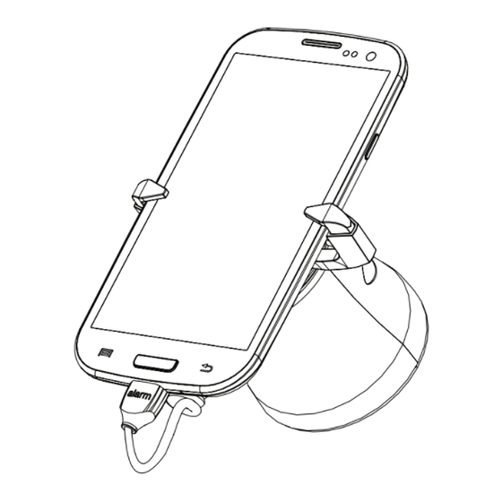
- Page 9 ATTACHING MERCHANDISE Wipe back of phone with alcohol wipe provided. Let it dry completely. Arms Power Connector Sensor...
- Page 10 Plug power connector into phone. Confirm phone is placed on sensor correctly so orien- tation of phone is correct on recoiler. Make sure cut out in sensor is towards top of phone. Top of Phone Cut out in sensor...
- Page 11 Remove clear film off adhesives on sensor. Center and Attach both arms to sensor. Confirm arms are fitted attach merchandise to sensor. Press firmly for at least to width of merchandise. Squeeze both arms against 10 seconds. merchandise and tighten screw with T-20 bit to lock arms in sensor.
- Page 12 Adjust arms to thickness of merchandise and tighten Attach sensor to recoiler. screw with T-20 bit. Do not overtighten.
- Page 13 Fully tighten both screws with T-20 bit. Optional. Lock screw with T-27 bit to prevent from lifting recoiler.
- Page 14 Arm/Disarm Alarm Place key on lens of IR Dot. Press grey button once to arm and disarm alarm.
- Page 15 Corporate Office (North America) // 704.752.6513 • 888.55.INVUE Europe, Middle East & Africa // +31.23.8900150 Asia Pacific // +65.6766.4844 Latin America // +52.55.9000.3957 © 2013 InVue Security Products Inc. All rights reserved. InVue is a registered trademark of InVue Security Products.
Need help?
Do you have a question about the High Security 200 and is the answer not in the manual?
Questions and answers