Table of Contents
Advertisement
Quick Links
Advertisement
Table of Contents

Related Manuals for IKA MICROSTAR control Series


Summary of Contents for IKA MICROSTAR control Series
- Page 1 MICROSTAR control...
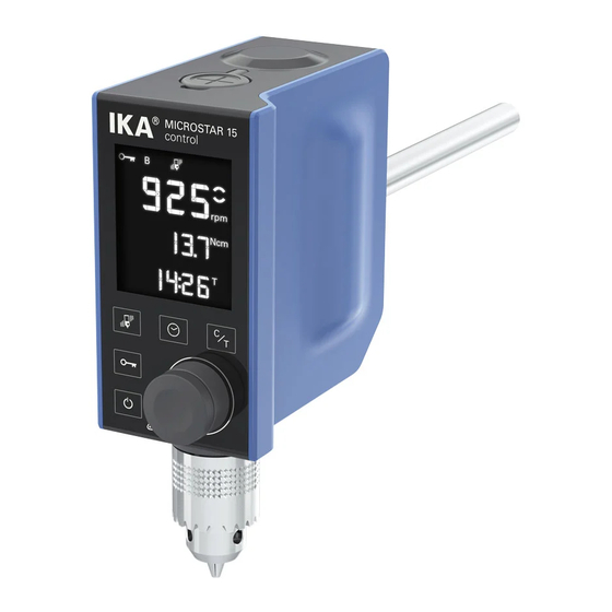
- Page 2 Device setup /// MICROSTAR control /// What you should watch out for Operator panel and display Chuck Extension arm Temperature sensor socket Power socket Attention! ( USB interface Stirring shaft cap Device setup Device setup...
-
Page 3: Safety Instructions
Safety instructions /// Explication of warning symbols /// General information › Read the operating instructions in full before starting up and follow the safety instructions. › Keep the operating instructions in a place where it can be accessed by everyone. ›... -
Page 4: Device Setup
Danger! ( Danger! ( Users must make sure that the OFF switch of the IKA device can be accessed Do not operate the device in explosive atmospheres, with hazardous immediately, directly and without risk at any time. If installation or positioning substances or under water. -
Page 5: Switch On / Off The Device
/// Accessories › Imbalance of the output shaft, the chuck and in particular the stirring › Protect the device and accessories from bumping and impacting. tools can lead to uncontrolled resonant vibrational behavior of the device › Check the device and accessories beforehand for damage each time and the whole assembly. -
Page 6: Correct Use
Correct use Unpacking /// Basics /// Scope of Delivery Unpack the device carefully. Any damage should be notified immediately to › For mixing / stirring liquids from low to medium viscosities the shipping agent (post office, railway network or logistics company). with various stirring tools. -
Page 7: Useful Information
Useful information /// Stirrer Power supply unit (with exchangeable adapters) The stirring device is suitable for continuous operation. The motor current is limited electronically. The device has an anti-stall and anti-overload system. If a fault occurs, a safety circuit immediately switches off the motor Europe permanently. -
Page 8: Operator Panel And Display
Display The clamping chuck and output shaft permit clamping IKA recommend stirrer Device switches on / enters standby tools (see section “Permitted IKA Stirrer tools“). The output shaft is designed Standby key (no disconnection from the power supply network). as a hollow shaft and the opening on the top side of the housing is closed Lock key Lock / unlock keys and knob. -
Page 9: Explanation Of Symbols On The Display
/// Explanation of symbols on the display The symbols appear on the screen change depending on the status Display and settings of the device. The following screen shows the most This symbol indicates all function keys except for the standby key (A) are locked. significant symbols. - Page 10 Assembly /// Assembling the extension arm /// Assembling the overhead stirrer to the overhead stirrer to the stand Cross sleeve Screw bolt Extension arm Stirrer Stand Extension arm Check that the stirrer is held in position firmly prior to each use and also at Hexagonal socket screw regular intervals.
- Page 11 Commissioning /// Assembling the stirring shaft protector /// Switching on Secure the device to a stable stand with a cross sleeve. Stirrer The stirring vessel must always be securely fixed for safety reasons. You must also ensure that the mounting device (stand) is set up in such a way that it is not liable to topple and does not start to move during the stirring procedure.
- Page 12 Setting speed Locking the keys and knob › Ensure the speed set is suitable for the test medium selected. If in doubt, By touching the lock key (B) about 2 seconds, you can lock the control elements set the speed to the lowest speed (counterclockwise direction) by rotating of the device.
- Page 13 /// Calibration Notice! ( ) Torque calibration: › Pressing the control knob (G) starts the torque calibration. Stirring tool must be removed from the chuck! In calibration mode the chuck rotates up to max. speed. The setting functions can be exited at any time by toucing the standby key (A).
-
Page 14: Interfaces And Outputs
Install the driver individual items of laboratory control equipment, rev. 1.1). by running the setup file. Then connect the IKA device through the USB data The NAMUR commands and the additional specific IKA co mmands serve only cable to the PC. The data communication is via a virtual COM port. -
Page 15: Maintenance And Cleaning
IN_NAME Read device name For cleaning disconnect the main plug! IN_PV_3 Read PT1000 value Use only cleaning agents which have been approved by IKA to clean IKA devices. IN_PV_4 Read current speed value IN_PV_5 Read current torque value Read rated speed value... -
Page 16: Error Codes
Please send in device for repair only after it has been cleaned and Err. 04 is free from any materials which may constitute a health hazard. For repair, please request the “Decontamination Certificate" form from IKA Cause › motor blockage or overload or download a print version from www.ika.com. -
Page 17: Warranty
Permitted IKA stirrer tools /// Regulations /// An overview According to IKA’s Terms and Conditions this product carries a lifetime Propeller stirrer warranty. For claims under the warranty please contact your local dealer. › R 1342 max. speed (rpm) ≤ 2,000 You may also send the machine direct to our factory, enclosing the delivery ›... -
Page 18: Technical Data
Technical data /// MICROSTAR control in detail Technical data MICROSTAR control MICROSTAR MICROSTAR 7.5 control | 15 control | 30 control 7.5 control | 15 control | 30 control Speed range under Max. output power 0 / 30 – 0 / 30 – 0 / 30 –...
Need help?
Do you have a question about the MICROSTAR control Series and is the answer not in the manual?
Questions and answers