
Related Manuals for REMKO ATR 10


Summary of Contents for REMKO ATR 10
- Page 1 Operating and installation instructions REMKO ATR Electronic temperature regulation ATR 10 Edition GB - N12 Read the instructions prior to performing any task!
-
Page 3: Table Of Contents
Contents Environmental protection and recycling Safety notes Controls Function description Clock Time program Control parameters 10-11 Default settings Setting overview Assembly Installation Customer data Circuit diagram 16-18 Technical data Carefully read this Installation manual prior to commis- sioning/using the units! This operating manual is a translation of the German original. -
Page 4: Environmental Protection And Recycling
Units may not be used in areas where ■ or the use of this documentation there is an increased risk of damage. for purposes other than intended is strictly prohibited without the written authorisation of REMKO GmbH & Co. KG is prohibited. -
Page 5: Controls
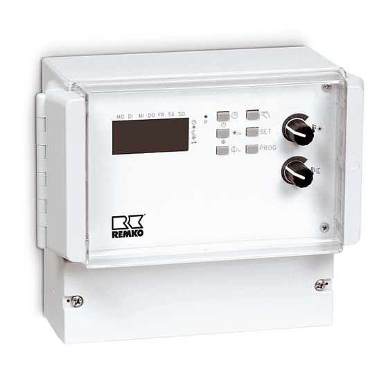
Controls 1 = Daytime temperature adjustment button 4 = Reset key (ATR-10 board) 2 = Nighttime temperature adjustment button 5 = Operating status indicators 3 = Program keys 6 = Operating mode indicators (H/L) Function description MO DI MI DO FR SA SO The weekly timer controls the daytime and nighttime temperatures in hourly ☾... - Page 6 REMKO ATR Nighttime temperature Depending on the selected units, "Heating or Ventilation", and additional relay out is activated for signalisation. The nighttime temperature is adjusted with the lower adjustment button [2]. The nighttime temperature MO DI MI DO FR SA SO is independent of the daytime temperature.
- Page 7 Hand key Reset key key is used to modify the current Three different reset options are available: temperature level in hourly operation. The selected temperature level is displayed on the right-hand side 1. Start-up reset: of the display with the indicators. This function is deleted with the next The R [4] key allows the unit to be program point.
-
Page 8: Clock
REMKO ATR Clock Time program The clock is a weekly timer with approx. The time program can be modified 4 hours of power reserve. by briefly pressing the PROG key. 16 program spaces are available. On initial commissioning or following... - Page 9 Pressing the SET key opens the settings Pressing the SET key again opens for the days of the week (flashing day the settings for the desired temperature indicators). values (flashing indicators in front of the respective temperature level). MO DI MI DO FR SA SO The following selection options are available: Pressing the + and –...
-
Page 10: Control Parameters
REMKO ATR Control parameters Default settings Pressing the PROG key for 3 seconds Pressing the PROG key for 6 seconds opens a menu in which the different opens a menu in which the different regulation parameters can be set. basic functions can be set. - Page 11 Sensor calibration Key lock SEnS (sensor calibration display) Loc (key lock) MO DI MI DO FR SA SO MO DI MI DO FR SA SO Pre-setting Limit Pre-setting Alternatives 0.0 K ±3.0 K (inactive) (active) Stabilised temperature values must be available for sensor calibration. Key lock prevents the daytime and In addition, sensor calibration must be nighttime temperatures from being...
-
Page 12: Setting Overview
REMKO ATR Setting overview Nighttime Default screen temperature ¹ 3 sec. Set time PROG PROG 1 sec. Time program PROG Set time 3 sec. program "diFF" control parameter PROG 6 sec. "SEns" default "Loc" key lock setting... -
Page 13: Assembly
Assembly The electronic temperature controller is suitable for wall mounting with NOTE a surface-mounted cable inlet. The external temperature probe NOTE must be installed such that The external temperature probe it can record the average room must, where possible, be fitted temperature. -
Page 14: Installation
REMKO ATR Installation De-energise all live lines before ■ Maximum line Line cross section working on the unit length Connections must be made 10 m 1.50 mm² ■ in accordance with the circuit diagram 15 m 1.50 mm² on page 16,17 and 18 20 m 2.00 mm²... -
Page 15: Customer Data
Customer data The following tables have been compiled for entering the individual customer data: Time program: Program point Start time Day(s) Temperature level Control parameters: Switching difference Functions: Sensor calibration We reserve the right to modify the dimensions and design as part of the ongoing technical development process. -
Page 16: Circuit Diagram
REMKO ATR Circuit diagram Ö1 Ö2 Ö3 Heat/ Heat/ Ventilate Ventilate PE L release selection NOTE CAUTION A mains voltage must be permanently Terminals P1 and S1 are available at terminals L and N used for connection for fault acknowledgement. - Page 17 Circuit diagram for one GPS unit ATR-10 A1 A2 T2 P1 S1 Ö1 P2 S2 Ö2 P3 S3 Ö3 N PE L Set selection Wahlschalter switch to NC auf NC stellen Temperature probe 363534333231 GPS board 1. GPS...
-
Page 18: Circuit Diagram
REMKO ATR Circuit diagram for GPS group operation ATR-10... -
Page 19: Technical Data
Technical data Type ATR-10 Daytime temperature + 5 to + 40°C Nighttime temperature - 5 to +25°C Temperature probe KTY (external) Probe tolerance ±1 K Switching difference ±0.1 to ±3.0 K, adjustable Temperature resolution Setpoint 0.5 K/actual value 0.1 K Setpoint temperature setting Rotary buttons, menu Program points... - Page 20 REMKO INTERNATIONAL ... and also right in your neighbourhood! Take advantage of our experience and advice REMKO GmbH & Co. KG Air conditioning and heating technology Im Seelenkamp 12 D-32791 Lage Postfach 1827 D-32777 Lage Telephone +49 5232 606-0 +49 5232 606-260 E-mail info@remko.de...
Need help?
Do you have a question about the ATR 10 and is the answer not in the manual?
Questions and answers