
Related Manuals for Riello RTT 39


Summary of Contents for Riello RTT 39
- Page 1 RTT 29-79 EN INSTRUCTIONS FOR THE INSTALLER AND FOR THE TECHNICAL ASSISTANCE CENTRE...
- Page 2 Technical Assistance Centre which is RTT 29 BOILER 20091169 specifically capable of carrying out routine maintenance, keep RTT 39 BOILER 20091170 it running at maximum efficiency, with low running costs and which has original spare parts if required. RTT 49 BOILER...
-
Page 3: Table Of Contents
CONTENTS 1.1 General warnings ....... 4 1.2 General characteristics of the RTT boiler ....5 1.3 Technical data. -
Page 4: General Warnings
1.1 General warnings panel and the boiler should be carried out by qualified personnel in compliance with the reference regulations and The boiler models in this manual are delivered fully assembled. standards. The burner should be purchased separately, this manual The cast iron boilersRTT 29-79 are designed for heating using contains only information regarding the boilers and the water and/or supplying hot water systems and have been... -
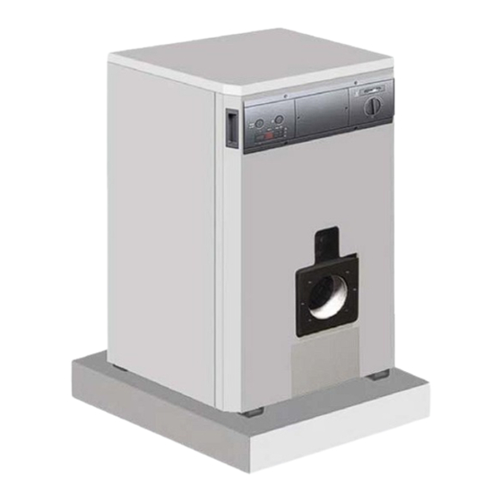
Page 5: General Characteristics Of The Rtt Boiler
1.2 General characteristics of the RTT boiler The RTT 29-79 boilers are forced draught heat generators, composed of cast iron elements, whose power ranges from 29.1 a 78.5 kW with an adequate connection to the burner and they operate with gas or liquid fuel, available in 6 different models. The maximum operating pressure of the RTT 29-79 boilers is 4 bar and the maximum operating temperature is 90°C. -
Page 6: Technical Data
1.3 Technical data RTT 29 RTT 39 RTT 49 RTT 59 RTT 69 RTT 79 RTT CAST IRON BOILER BOILER BOILER BOILER BOILER BOILER BOILER Number of sections pieces 29.1 39.0 48.8 58.7 68.6 78.5 Heat output 25,000 33,500 42,000... -
Page 7: Boiler Data Plate
1.4 Boiler data plate BOILER BOILER BOILER BOILER BOILER BOILER RTT 29 RTT 39 RTT 49 RTT 59 RTT 69 RTT 79 The data plate is applied to the rear of the boiler shell. 1,010 (mm) 1.5 Overall dimensions 1.6 Delivery The RTT 29-79 boilers are mounted on a wood pallet wrapped with Pluriball and inside a wood box. -
Page 8: Installation Of The Boiler
600 mm that part. On the other part, half the indicated free distance is sufficient. RTT 29 RTT 39 RTT 49 RTT 59 RTT 69 RTT 79 Provide enough space for the tools to be used in the boiler room. -
Page 9: Important Instructions For The Boiler
1.8 Important instructions for the boiler 1.9 Hydraulic system Limescale and other chemical substances in the water can so- The boiler room should be well lit and the light switches lidify producing incrustations. To prevent this happening, equip should be located outside the room itself. the system with a closed expansion tank. -
Page 10: Schematic Diagram - System For Heating And Domestic Hot Water Production
1.10 Schematic diagram - system for heating and domestic hot water production DOMESTIC SYSTEM Boiler System Manifolds SYSTEM WATER RETURN Shut-off valves OUTLET UTILITIES LINE System pumps Non-return valves Automatic vent valve Boiler safety valve Boiler discharge tap Storage heater safety valve 10 Charging the system System expansion tank 12 Storage heater... -
Page 11: Important Information About The Flue Pipe
1.12 Important information about the flue gases pipe 1.13 Standard control panel of the boiler Low flue edge Thick section Flue without ridge Humidity Cracks Another boiler on same flue Connection betwee two flue lines Objects blocking gas flow Bad surface,dust etc.. Blocking gas flow Dust obstacling cleaning Flue which is not available for cleaning Weakly closed door... -
Page 12: Cast Iron Sections With High Performance System With Three Flue Passes
Optimised combustion chamber with complete heat (***) Lower part part part part insulation gets the highest yield from the fuel. BOILER RTT 29 RTT 39 BOILER RTT 49 BOILER 3rd pass RTT 59 BOILER 2nd pass RTT 69 BOILER... -
Page 13: Gas Side Resistor, Temperature Of Output Flue Gases
1.18 Gas side resistor, temperature of output flue When faced with any fault (contactor, temperature swings, gases interruption of current, other faults), or when the pumps are stopped (protection pumps, etc.) the burner should switch off. The system should do this automatically. Carry out the electrical wiring taking into account all the Full Load above-mentioned information. -
Page 14: Fire Prevention Regulations For The Boiler Room
1.22 Fire prevention regulations for the boiler above 40°C before starting the pumps, the circulation pump room and the burner should operate contemporaneously. − Start the burner (carrying out the commands described in The RTT boilers should be positioned and oriented carefully and the burner's instruction manual). -
Page 15: Checking The Safety Limit Thermostat
1.27 Checking the safety limit thermostat Annual checks The annual checks should be carried out by technicians before the start of the season. The flue gases pipe and the relative pipes need to be cleaned before requesting the intervention of tech- nicians for the annual checks. -
Page 16: Connecting The Door Of The Burner And The Boiler
1.30 Connection of the burner door and the 1.31 Dimensions of the connection flange of the burner burner Burner door RTT 29-39 Fix the burner without leaving any empty space between the front door and the burner head. Cover all the connection points with insulating material to prevent leaks. -
Page 17: Table Of Burner Combinations
1.32 Table of burner combinations OIL BURNER BURNER BOILER MODEL CODE 3772117 BOILER RTT 29 REG 35.3 3772217 RTT 39 BOILER REG 35.5 3737700 RTT 49 BOILER 3737700 RTT 59 BOILER 20051874 RTT 69 BOILER 20051874 RTT 79 BOILER DOUBLE FUEL BURNER... -
Page 18: Removal Of Flue Gases
1.33 Removal of flue gases The design of the flue gases discharge system should be carried out following current standards. The flue should be rigid, completely air-tight, heat resistant, as well as resistant to condensation and mechanical stresses. If done incorrectly, the smoke pipe can increase noise or con- densation could form inside it, compromising the boiler's per- formance. -
Page 19: Useful Information
1.35 Useful information Retailer: ................Installer: ................Mr.: .................. Mr.: .................. Address: ................Address: ................Tel.: .................. Tel.: .................. Technical Assistance Centre: ..........Mr.: .................. Address: ................Tel.: .................. Date Intervention Fuel supplier: ..............Mr.: .................. Address: ................Tel.: .................. Date Qty supplied Date... - Page 20 RIELLO S.p.A. 37045 Legnago (VR) Tel. 0442630111 - Fax 044222378 - www.riello.it As part of the company’s ongoing commitment to perfecting its range of products, the appearance, dimensions, technical data, equipment and accessories may be subject to variation.
Need help?
Do you have a question about the RTT 39 and is the answer not in the manual?
Questions and answers