Advertisement
Quick Links
Advertisement

Related Manuals for Riello RTT 378


Summary of Contents for Riello RTT 378
- Page 1 RTT 378-930 EN ASSEMBLY MANUAL...
- Page 2 − 2009/142/EC (ex 90/396/EEC-Gas Directive) − 92/42/EEC (Efficiency Directive) − 2006/95/EC (ex 73/23/EEC-Low voltage Directive) ACCESSORIES − 2004/108/EC (ex 89/336/EEC-Electromagnetic Compatibility For the RTT 378-930 r boilers the following accessories are avail- Directive) able: − EN 303/1-2-3 − EN 60335-1/2 Two stage kit –...
- Page 3 1.1 INSTALLATION SPECIFICATIONS OF RTT CAST IRON BOILERS This manual is for personnel authorised and qualified to install and provide technical assistance both domestically and over- seas and should be used in order to correctly install the cast iron boiler. The technical personnel should always put the machine in a safe condition both before and during installation.
- Page 4 • Install the frame for assembling the boiler (with the • Clean the grooved flue gas seal of the rear section with a equipped part facing the other and facing back) on the con- brush or a cloth, then insert the silicon. crete plate.
- Page 5 • After applying the insulating cord, the axle connection and • After installing the intermediate sections, do the same also the O-ring to the rear section, install the intermediate sec- for the front section. tion sliding it on the frame. •...
- Page 6 • Insert the expanding springs, nuts and bolts as indicated in • After installing the boiler's water inlet and outlet attach- the figure below. ments, check that the appliance is waterproof by putting in • The distance of the spring joints should be about 0.5 mm. water for 10 minutes at a pressure of 9 bar without connect- •...
- Page 7 Second pass Third pass • Attach the door, fixing it with 4 M10x80 mm bolts according to the side you want to open and based on the hydraulic RTT 378 1+1+1+1 1+1+1+1 connections and the boiler room. • After inserting the bolts, fix them with 4 M16 nuts and bolts...
- Page 8 Section numbers assembly sembly Number brackets Detail of brackets Casing of casing Model casing connecting as- length assembly 1090 RTT 378 1.2+3.4+5.6 assembly sembly shelves 1,250 shelves RTT 448 1.2.+4.5+6.7. RTT 378 1,090 front+4.5+back 1,410 RTT 506 1.2.+4.5.+7.8. FRONT...
- Page 9 • Prepare 8 cm of insulation for the boiler body based on the dimensions of the appliance and apply it to the boiler body. • Cut the insulation around the points connecting the assem- bly shelves. • After installing the brackets and shelves of the casing walls, •...
- Page 10 • Line up the holes on the walls of the casing first with the pins on the assembly brackets and then with the assem- bly shelves of the casing walls, fixing them with two M8x20 bolts as shown in the figure. •...
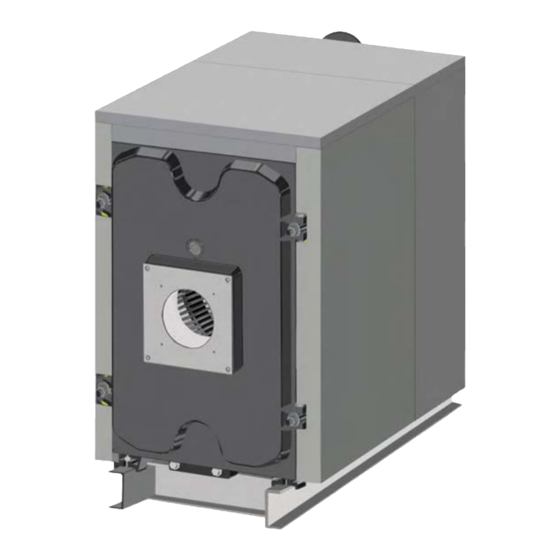
- Page 11 • Once this operation has been carried out, the installation of the casing walls is complete. • After installing the side and top walls of the casing, install the rear one. • At this point the boiler is ready for the installation of the burner and for the flue gases pipe connections.
- Page 12 RIELLO S.p.A. 37045 Legnago (VR) Tel. 0442630111 - Fax 044222378 - www.riello.it As part of the company’s ongoing commitment to perfecting its range of products, the appearance, dimensions, technical data, equipment and accessories may be subject to variation.
Need help?
Do you have a question about the RTT 378 and is the answer not in the manual?
Questions and answers