
Related Manuals for Climax BB5500


Summary of Contents for Climax BB5500
- Page 1 BB5500 BORING MACHINE OPERATING MANUAL SERIAL NUMBER RANGE: 11017900 - 11021000 ORIGINAL INSTRUCTIONS P/N 29327 May 2019 Revision 3...
-
Page 3: Table Of Contents
TABLE OF CONTENTS TABLE OF CONTENTS ............................1 General Safety ............................... 3 Machine Specific Safety ............................4 Labeling Guidelines ..............................5 Risk assessment and hazard mitigation ........................ 6 Risk assessment checklist ............................. 7 Warning Labels ..............................8 CE Mark ................................. 9 Introduction................................ - Page 4 CLIMAX warrants that all parts are free from defects in materials and workmanship, and that all labor has been performed properly. This warranty is available to the customer purchasing parts or labor for a period of 90 days after delivery of the part or repaired machine or 180 days on used machines and components.
-
Page 5: General Safety
The primary challenge for most on-site maintenance is that repairs are often done under difficult conditions. Climax Portable Machining & Welding Systems leads the way in promoting the safe use of portable machine tools. Safety is a joint effort. As the operator of this machine, you are expected to do your part by scrutinizing the job site and closely following the operating procedures outlined in this manual, your own company rules, and local regulations. -
Page 6: Machine Specific Safety
Machine Specific Safety All aspects of the machine have been designed with safety in mind. Following are safety practices that you should keep in mind when using the Climax BB7000 Boring Bar Machine. PERSONAL PROTECTIVE EQUIPMENT HAZARDOUS ENVIRONMENTS Eye and hearing protection must be worn while using the Do not use the machine in a hazardous environment, machine. -
Page 7: Labeling Guidelines
Labeling Guidelines The purpose of product safety signs and labels is to increase the level of awareness to possible dangers. Safety alert symbols indicate DANGER, WARNING or CAUTION. These symbols may be used in conjunction with other symbols or pictographs. Failure to obey safety warnings can result in serious injury. -
Page 8: Risk Assessment And Hazard Mitigation
Due to the unique nature of portable machining applications, identifying one or more hazards that must be addressed is typical. When performing the on-site risk assessment, it is important to consider the Portable Machine Tool and the workpiece as a whole. Page 6 BB5500 Operating Manual... -
Page 9: Risk Assessment Checklist
Risk assessment checklist Use these checklists as part of your on-site risk assessment and include any additional considerations that may pertain to your specific application. 1. R ABLE ISK ASSESSMENT CHECKLIST BEFORE SET Before Set-up I took note of all the warning labels on the machine. ... -
Page 10: Warning Labels
Warning Labels The following labels are affixed to the machine. If these are damaged or lost, call Climax immediately for replacements. Page 8 BB5500 Operating Manual... -
Page 11: Ce Mark
Sound levels are under 85 dBA, hearing protection not required. The preceding sound information is for the BB5500 machine only. The power supply which is used with the BB5500 machine will increase the sound levels and may necessitate the use of hearing protection. -
Page 12: Introduction
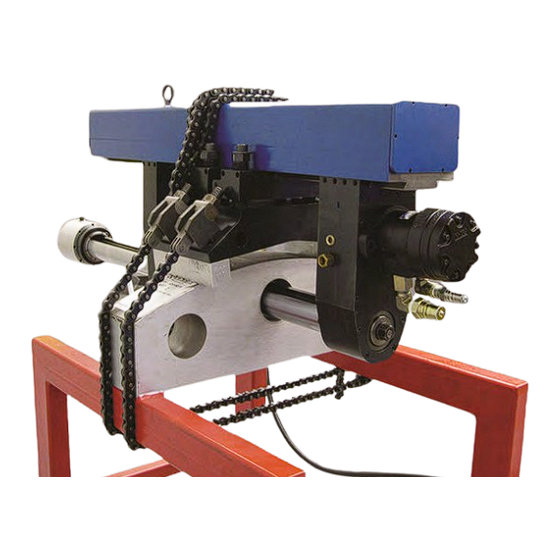
The extremely rigid and compact BB5500 enables just one operator to set up the machine and quickly bore precisely aligned bolt holes the first time. The feed bar removal feature enables the operator to measure and inspect the bore without the need to re-set the machine. - Page 13 Climax BB5500 Components P/N 29327, Rev. 3 Page 11...
-
Page 14: Receiving Your Machine
Receiving Your Machine The Climax Model BB5500 was run tested and thoroughly inspected before leaving the factory. When leaving the factory, the machine is packaged well for the demands of normal transportation. Climax cannot, however, guarantee the condition upon arrival of the machine. -
Page 15: Setup
The machine is equipped with a form fitted container for storage and shipping. With a modular design, the machine can be broken down into components to ease setup. Climax recommends using a sling or other suitable lifting device. The machine is fitted with two lifting eyes which serve as stable lift points. - Page 16 Remove the Lower Bearing Hanger and Boring Bar Do the following to remove the lower bearing hanger and boring bar. 1. Loosen the clamp assembly. 2. Remove the lower bearing hanger assembly and the boring bar at the same time. Page 14 BB5500 Operating Manual...
- Page 17 CAUTION Use caution when handling the lower bearing hanger assembly and boring bar. These assemblies are heavy. Dropping them can cause damage to the machine and personal injury. Centering the Strongback Supports Center the strongback supports before mounting the machine onto the work piece. Centering the strongback supports to make sure you have the maximum amount of room to properly adjust the boring bar within the work piece.
- Page 18 Turn the socket set screws out on either side of the support. The amount of space between the set screw and the strongback support should be equal on both sides. Repeat the procedure for the other support. Center the machine horizontally. Page 16 BB5500 Operating Manual...
- Page 19 • an indicator or other measuring instrument to help you align the bar later on during setup. IMPORTANT For optimum results, Climax recommends the following bearing spacing: • 1-3/8 inch diameter bar up to 11 inches with a bore diameter of 1-1/2 inch •...
- Page 20 3. The shim will equal the number at the top of the table. The shim you choose will allow up to 1/4 inch of play, which can be compensated for by other machine adjustments. Spacer Shim Example with 40” coupling outer diameter and 35” bolt circle diameter Page 18 BB5500 Operating Manual...
- Page 21 Coupling 0 shim 0.25 0.75 1.25 1.75 Diameter 18.7 19.2 19.8 20.3 20.8 21.3 21.9 22.4 19.8 20.3 20.9 21.4 21.9 22.4 23.0 23.5 20.9 21.4 21.9 22.5 23.0 23.5 24.0 24.6 22.0 22.5 23.0 23.5 24.1 24.6 25.1 25.6 23.1 23.6 24.1...
- Page 22 Special spacer blocks are available for couplings with large OD’s (compared to the bolt circle diameter). These spacers decrease the bolt circle size in the table by 4”, 8” or 12” inches, depending on how they are stacked. Call your Climax sales representative for information on this option.
- Page 23 Spacing the Machine off the Coupling Setting the Machine on the Work Piece Adjustments to bring the centerlines into precise alignment are made with jacking bolts on the strongback support after the machine is mounted. Set the machine on the workpiece. Before you set the machine onto the work piece make sure the strongback supports and bearing assembly are positioned to meet the needs of your application.
- Page 24 5. Evenly tighten the two chain clamp nuts on each side of the machine. IMPORTANT When tightening the chain onto the rocker and large casting block, make sure the top of the chain assembly does not contact the base strongback support. Page 22 BB5500 Operating Manual...
- Page 25 Installing the Bearing Hanger Make sure the gibs on the upper bearing hanger and RDU are both on the same side. Failure to keep the gib on the same side prevents the boring bar from aligning and will cause the bar to bind. Installing the RDU (Rotational Drive Unit) Make sure the gib is on the same side of the strongback supports as the gib on the RDU.
- Page 26 RDU. Make sure the drive keys are properly engaged with the drive gear and tighten securely. 5. At this point, go over the entire machine and make sure all of the bolts and screws are tight. Page 24 BB5500 Operating Manual...
- Page 27 Aligning the Boring Bar within the Work Piece To align the machine to the workpiece, use a scale for preliminary alignment and a dial indicator for a final measurement. Which procedures you follow when aligning the machine to the work piece depends on the level of precision you need. Use a scale (such as a ruler) or a dial indicator depending on your precision needs.
- Page 28 5. Adjust the speed of bar rotation by turning the motor speed control (a knob located on the operator pendant). Operator pendant Page 26 BB5500 Operating Manual...
- Page 29 There are three types of feed boxes available. The single direction mechanical feed. The reversible mechanical feed - PN 47287 The electric feed. Please see your Climax Sales Representative about details for this option. Install the Single-Direction Mechanical or Electrical Feed The axial feed unit can be used with or without the bar rotating in manual mode.
- Page 30 When the feed selector is in the neutral position, there will be no feed and the crank handle can be used to position or retract the tool slide. Page 28 BB5500 Operating Manual...
- Page 31 When the feed selector is in the full retracted position, the tool slide will feed towards the feed box. WARNING You, the operator, must monitor the tool slide position. Over- travel of the tool slide in either direction will result in damage to the machine.
- Page 32 1/100 of the travel range. 10-15 turns of the bar are necessary to change the feed rate approximately .001” per revolution. The amount of feed is shown by the feed indicator. The length of the red engraved line on the feed indicator shows the relative feed amount. Page 30 BB5500 Operating Manual...
- Page 33 Tooling Setup The Climax Model BB5500 has a traveling tool slide controlled by the leadscrew and axial feed unit. The tool slide has a rectangular pocket that accepts a variety of tool holders which are available for different bore diameter ranges and tooling types. The tool holders included are pictured below.
- Page 34 Always place the tool holder completely in the pocket of the tool slide and secure with the two setscrews provided in the tool slide. IMPORTANT Excessive clearance in the tool slide can affect final finish and tolerance of the bore. Page 32 BB5500 Operating Manual...
- Page 35 Setting up the high speed steel tool There are two setscrews positioned diagonally on the top surface of the high speed steel tool holder. These screws allow the radial position of the tool bit to be micro adjusted. The high speed steel tool holder has two setscrews that clamp the tool bit in the broached hole.
- Page 36 5. Turn the lock screw until there is slight spring tension on the washers. Do not over- tighten to allow for further adjustability from the dial nut. 6. Install the tool holder on the tool slide. 7. Turn the dial nut to the desired position. Page 34 BB5500 Operating Manual...
- Page 37 Setting up the cartridge The cartridge holder includes a tool for changing the inserts and an adjusting wrench for adjusting the radial position of the tool holder. The Microbore cartridge uses spring tension from washers located underneath the cartridge to hold the cartridge in place.
- Page 38 (72.9) 2.650 3.154 2.730 3.234 78342 (67.3) (80.1) (69.3) (82.1) No. 3 3.145 3.649 3.225 3.729 Microbore 78343 (PN 78359) (79.9) (92.7) (81.9) (94.7) Insert 78421 3.635 4.139 3.720 4.224 78344 (92.3) (105.1) (94.5) (107.3) Page 36 BB5500 Operating Manual...
-
Page 39: Operation
Operation Pre-start Checks Before operating the machine, check that: All machine parts, including the tool head, tool bit, gib key setscrews, draw bolt, tapered dovetail way clamp and collar clamps are secure. The power is connected and turned on. ... - Page 40 9. RUN/JOG—in RUN mode, the feed moves automatically. In JOG mode, the feed can be advanced by pressing the FEED start button and will stop when the button is released. 10. FWD/REV—changes the direction of the tool feed. Page 38 BB5500 Operating Manual...
-
Page 41: Disassembly
Disassembly Do the following to disassemble the machine. 1. Turn off the hydraulic power unit. 2. Remove the axial feed box assembly. 3. Retract the tool holder. 4. Loosen the bearing cartridge collar. 5. Loosen the rotational drive draw bolt. 6. -
Page 42: Maintenance
Maintenance Maintenance Items Follow the list below when maintaining your BB5500 Portable Boring Machine. Mounting assembly: Inspect the dovetail ways, clean, lubricate, and carefully remove any burrs. Boring bars: Handle boring bars carefully to prevent damage. Inspect the taper and carefully remove any burrs. -
Page 43: Storage
Storage Proper storage protects the machine from damage and corrosion. 1. Before storing, clean the machine with solvent to remove grease, metal chips, and moisture. 2. Spray with a light oil for short-term storage or use diesel for long-term storage to prevent corrosion. -
Page 44: Specifications
Gear / Drive ratio 1.13:1 Torque produced 2.2 cubic inch HPU: 22 ft. lbs. 3.6 cubic inch HPU: 40 ft. lbs. 5.9 cubic inch HPU: 65 ft. lbs. Perpendicularity and alignment are dependant on operator setup. Page 42 BB5500 Operating Manual... -
Page 45: Exploded Views And Parts
The following diagrams and parts lists are for your reference purposes only. The machine Limited Warranty is void if the machine has been tampered with by anyone who has not been authorized in writing by Climax Portable Machining & Welding Systems to perform service on the machine. - Page 46 BEARING CARTRIDGE 2-1/2 ID X 4.9213 OD (STRAIGHT) 29044 HANGER BEARING LOWER 2-1/2 DIA STRAIGHT 25625 CLAMP ASSEMBLY BEARING HANGER 10160 SCREW 1/4-20 X 3/4 SHCS Figure 3 - Hanger Bearing Lower 1-7/8 Dia Bar 27294 2-1/2” Dia Bar 29043 Page 44 BB5500 Operating Manual...
- Page 47 27295 HANGER BEARING ASSEMBLY LOW ER 2-1/2 DIA BAR SPHERICAL BALLOON NO PART DESCRIPTION 25502 BEARING CARTRIDGE 2-1/2 ID X 4.9213 OD SPHERICAL 25624 HANGER BEARING LOWER 2-1/2 DIA SPHERICAL 25625 CLAMP ASSEMBLY BEARING HANGER 10160 SCREW 1/4-20 X 3/4 SHCS Figure 4 - 27295 Hanger Bearing Lower 2-1/2 Dia Bar Spherical P/N 29327, Rev.
- Page 48 Page 46 BB5500 Operating Manual...
- Page 49 27285 BAR BORING ASSEMBLY 2-1/2 DIA X 36 LONG BALLOON NO PART DESCRIPTION 25461 BAR BORING 2-1/2 DIA X 36 IN. LG. 25631 KEY BORING BAR 12418 SCREW 1/4-20 X 5/8 SHCS 11165 WASHER THRUST .625 ID X 1.125 OD X .060 10538 BEARING THRUST .625 ID X 1.125 OD X .0781 25532...
- Page 50 Figure 5 - 27285 & 28765 Bar Boring 2-1/2 Dia Page 48 BB5500 Operating Manual...
- Page 51 P/N 29327, Rev. 3 Page 49...
- Page 52 Page 50 BB5500 Operating Manual...
- Page 53 P/N 29327, Rev. 3 Page 51...
- Page 54 Page 52 BB5500 Operating Manual...
- Page 55 P/N 29327, Rev. 3 Page 53...
- Page 56 Page 54 BB5500 Operating Manual...
- Page 57 P/N 29327, Rev. 3 Page 55...
- Page 58 Page 56 BB5500 Operating Manual...
- Page 59 P/N 29327, Rev. 3 Page 57...
- Page 60 Page 58 BB5500 Operating Manual...
- Page 61 P/N 29327, Rev. 3 Page 59...
- Page 62 Page 60 BB5500 Operating Manual...
Need help?
Do you have a question about the BB5500 and is the answer not in the manual?
Questions and answers