
Related Manuals for ACS AET60 BioCARDKey


Summary of Contents for ACS AET60 BioCARDKey
- Page 1 AET60 BioCARDKey Reference Manual info@acs.com.hk Subject to change without prior notice www.acs.com.hk...
-
Page 2: Table Of Contents
Appendix C. Recommended Device Cleaning Procedures.......... 24 Appendix C.1. Introduction ........................24 Appendix C.2. Periodic Cleaning .......................24 Appendix C.3. User Cleaning ......................24 Page 2 of 24 AET60 Reference Manual info@acs.com.hk Document Title Here Document Title Here Document Title Here Version 1.7 www.acs.com.hk... -
Page 3: Introduction
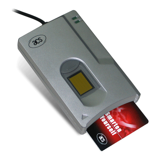
1.0. Introduction The ACS AET60 BioCARDKey is a device which combines a fingerprint scanner and a smart card reader/writer. The fingerprint scanner (TouchChip) makes use of the Active Capacitive-Sensing Technology from STMicroelectronics. The reader/writer part enables the communication between a computer (for example, a PC) and a smart card. -
Page 4: Fingerprint Scanner
2. False Rejection Rate (FRR): FRR is the rate at which the system incorrectly rejects a legitimate attempt to verify. Page 4 of 24 AET60 Reference Manual info@acs.com.hk Document Title Here Document Title Here Document Title Here Version 1.7... -
Page 5: Smart Card Reader
For microcontroller-based smart cards only the contacts C1 (VCC), C2 (RST), C3 (CLK), C5 (GND) and C7 (I/O) are used. A frequency of 4 MHz is applied to the CLK signal (C3). Page 5 of 24 AET60 Reference Manual info@acs.com.hk Document Title Here Document Title Here Document Title Here Version 1.7... -
Page 6: Card Tearing Protection
NOTE: The BioCARDKey never does by itself switch on the power supply to the inserted card. This action must be explicitly done by the controlling computer through the proper command sent to the reader. Page 6 of 24 AET60 Reference Manual info@acs.com.hk Document Title Here Document Title Here Document Title Here Version 1.7... -
Page 7: Power Supply
Red LED on the front of the reader indicate the activation status of the smart card interface: Red LED Indicates power supply to the smart card is switched on, i.e., the smart card is activated. Page 7 of 24 AET60 Reference Manual info@acs.com.hk Document Title Here Document Title Here Document Title Here Version 1.7 www.acs.com.hk... -
Page 8: Usb Interface
Differential signal transmits data between BioCARDKey and PC. Reference voltage level for power supply NOTE: In order for the BioCARDKey to function properly through the USB interface, ACS PC/SC device driver has to be installed. Please refer to the BioCARDKey Device Driver Installation Guide for more detail. -
Page 9: Pc-Reader Communication Protocol
The following example shows the structure of a command with instruction code = 91 and three data bytes with the values 11 , 22 and 33 , respectively: byte Page 9 of 24 AET60 Reference Manual info@acs.com.hk Document Title Here Document Title Here Document Title Here Version 1.7 www.acs.com.hk... -
Page 10: Extended Command
Checksum The checksum is computed by XORing all command bytes including header, instruction, data length and all data bytes. Page 10 of 24 AET60 Reference Manual info@acs.com.hk Document Title Here Document Title Here Document Title Here Version 1.7 www.acs.com.hk... -
Page 11: Response
The following example shows the structure of the response to a command which has successfully been executed and which returns three data bytes with the values 11 , 22 and 33 , respectively: byte Page 11 of 24 AET60 Reference Manual info@acs.com.hk Document Title Here Document Title Here Document Title Here Version 1.7 www.acs.com.hk... -
Page 12: No Transmission Error With Extended Response
If the computer detects a transmission error in a response from the BioCARDKey, it can send the 'NOT ACKNOWLEDGE' to the reader upon which the reader will transmit the most recent response again. Page 12 of 24 AET60 Reference Manual info@acs.com.hk Document Title Here Document Title Here Document Title Here Version 1.7... -
Page 13: Reset Message
(see Appendix B: Response Status Codes). Page 13 of 24 AET60 Reference Manual info@acs.com.hk Document Title Here Document Title Here Document Title Here Version 1.7... -
Page 14: Transmission Protocol
STX '0' 'f' ETX In its response messages, the BioCARDKey uses upper case characters 'A' ... 'F'. Page 14 of 24 AET60 Reference Manual info@acs.com.hk Document Title Here Document Title Here Document Title Here Version 1.7 www.acs.com.hk... -
Page 15: Smart Card Commands
Indicates whether a card is physically inserted in the reader and whether the card is powered up: : no card inserted : card inserted, not powered up : card powered up Page 15 of 24 AET60 Reference Manual info@acs.com.hk Document Title Here Document Title Here Document Title Here Version 1.7 www.acs.com.hk... -
Page 16: Set_Protocol
The new protocol becomes effective by the completion of the SET_PROTOCOL command, immediately after the BioCARDKey has sent out the response string to the SET_PROTOCOL command. Page 16 of 24 AET60 Reference Manual info@acs.com.hk Document Title Here Document Title Here Document Title Here Version 1.7... -
Page 17: Select_Card_Type
T=0 card and 90 01 when the inserted card is a T=1 card, otherwise the status code is 60 20 Page 17 of 24 AET60 Reference Manual info@acs.com.hk Document Title Here Document Title Here Document Title Here Version 1.7... -
Page 18: Set_Notification
: baud rate to/from the card is from 9600 bps to 115200 bps (default) : baud rate to/from the card is at 9600 bps only Response data format No response data Page 18 of 24 AET60 Reference Manual info@acs.com.hk Document Title Here Document Title Here Document Title Here Version 1.7 www.acs.com.hk... -
Page 19: Card Commands (Mcu-Based Card)
This command powers off the card inserted in the card reader. Command format Instruction Data length Code Response data format No response data Page 19 of 24 AET60 Reference Manual info@acs.com.hk Document Title Here Document Title Here Document Title Here Version 1.7 www.acs.com.hk... -
Page 20: Exchange_Apdu
Response data format BYTE BYTE BYTE x Response data from card (if any) SW1, SW2 Status code returned by the card. Page 20 of 24 AET60 Reference Manual info@acs.com.hk Document Title Here Document Title Here Document Title Here Version 1.7 www.acs.com.hk... -
Page 21: Exchange_T1_Frame
T1 Block frame to be sent to the card Response data format BYTE 1 BYTE N BYTE x Response T1 Block from card (if any) Page 21 of 24 AET60 Reference Manual info@acs.com.hk Document Title Here Document Title Here Document Title Here Version 1.7 www.acs.com.hk... -
Page 22: Appendix A. Supported Card Types
Type Code Auto-select T=0 or T=1 communication protocol MCU-based cards with T=0 communication protocol MCU-based cards with T=1 communication protocol Page 22 of 24 AET60 Reference Manual info@acs.com.hk Document Title Here Document Title Here Document Title Here Version 1.7 www.acs.com.hk... -
Page 23: Appendix B. Response Status Codes
Secret code locked APDU command aborted (only MCU-based card using T=1 protocol); the command abortion may be caused by a card internal failure. Page 23 of 24 AET60 Reference Manual info@acs.com.hk Document Title Here Document Title Here Document Title Here Version 1.7... -
Page 24: Appendix C. Recommended Device Cleaning Procedures
With this action we assure that residue from previous usage will be removed hence giving the best surface conditioning. Page 24 of 24 AET60 Reference Manual info@acs.com.hk Document Title Here Document Title Here Document Title Here Version 1.7...
Need help?
Do you have a question about the AET60 BioCARDKey and is the answer not in the manual?
Questions and answers