Table of Contents
Advertisement
Quick Links
Honeywell Life Safety Iberia
C/Pau Vila 15-19
08911 BADALONA (BARCELONA)
Tel.: 902 03 05 45
www.honeywelllifesafety.es
ST.PL4+
MANUAL DE USUARIO E INSTALACIÓN
INSTALLATION AND USER MANUAL
Toda la información contenida en este documento puede ser modificada sin previo aviso.
Information in this document is subject to change without notice.
MN-DT-516 / (MT3910)
13 JUNIO 2017 / 13 JUNE 2017
Advertisement
Table of Contents

Related Manuals for Honeywell Notifier ST.PL4+


Summary of Contents for Honeywell Notifier ST.PL4+
- Page 1 Honeywell Life Safety Iberia C/Pau Vila 15-19 08911 BADALONA (BARCELONA) Tel.: 902 03 05 45 www.honeywelllifesafety.es ST.PL4+ MANUAL DE USUARIO E INSTALACIÓN INSTALLATION AND USER MANUAL Toda la información contenida en este documento puede ser modificada sin previo aviso. Information in this document is subject to change without notice.
- Page 2 Manual de usuario e instalación / Installation and user manual PL4+ MN-DT-516.doc 13/06/2017 2 de 33 (MT3910.doc)
-
Page 3: Table Of Contents
Manual de usuario e instalación / Installation and user manual PL4+ ÍNDICE INDEX Características técnicas ................... 7 Technical specification ..................7 Fusibles ......................7 Fuses ....................... 7 Fijación mecánica .................... 8 Mechanical fixing ..................... 8 Diagram and part identification ................ 9 Equema del circuito base ................ - Page 4 Manual de usuario e instalación / Installation and user manual PL4+ Over range alarm ................... 22 Ejemplo de programación de una entrada ............. 24 Example of input channel programming ............24 Programación de entrada de detector de oxígeno ..........27 Oxygen detector input channel programming ..........
- Page 5 Manual de usuario e instalación / Installation and user manual PL4+ Avisos Warning TODA PERSONA RESPONSABLE DE LA THIS MANUAL MUST BE CAREFULLY READ INSTALACIÓN, USO O MANTENIMIENTO DE BY ALL PERSONS WHO HAVE OR WILL ESTE EQUIPO DEBE LEER EL MANUAL CON HAVE RESPONSIBILITY ATENCIÓN.
- Page 6 Manual de usuario e instalación / Installation and user manual PL4+ INTRODUCCIÓN INTRODUCTION La central PL4+ permite el reconocimiento de The PL4+ gas control panel can manage 4 señales del tipo 4-20mA procedentes de analogue 4-20mA gas detectors and can be sensores de gas.
-
Page 7: Características Técnicas
Manual de usuario e instalación / Installation and user manual PL4+ Características técnicas Technical specification Cabina ABS IP65 Housing ABS IP65 box: 486 x 288 x 148 mm 486 x 288 x 148 mm Tensión de alimentación 220VcA +/- 10% Power supply 100-240 Vac Consumo en reposo... -
Page 8: Fijación Mecánica
Manual de usuario e instalación / Installation and user manual PL4+ INSTALACIÓN INSTALLATION Fijación mecánica Mechanical fixing Antes de instalar la central, lea atentamente Before installing the control panel, read and y siga las instrucciones que se detallan a strictly follow the instructions detailed here continuación. -
Page 9: Diagram And Part Identification
Manual de usuario e instalación / Installation and user manual PL4+ Si la instalación requiere la conexión de una If the installation requires the connection to a back batería de apoyo, coloque la batería en la parte up battery, connect the wires to the battery side and superior izquierda de la cabina, justo por encima place the battery in the upper left side, just above de la barra metálica, y conecte los cables, tal y... -
Page 10: Equema Del Circuito Base
Manual de usuario e instalación / Installation and user manual PL4+ Equema del circuito base Main board layout La siguiente figura muestra la placa base The above figure shows the PCB mounted on montada en la parte posterior de la puerta frontal, the rear side of the front door, to which gas donde se conectará... -
Page 11: 2.3.1 Selección De Idioma
Manual de usuario e instalación / Installation and user manual PL4+ 2.3.1 Selección de idioma 2.3.1 Language Selection Es posible seleccionar el idioma de los It is possible to select the language for the mensajes que se visualizan en pantalla a través messages being displayed, via the SD1 de los microinterruptores del DIP SD1 del panel switches on the panel board... - Page 12 Manual de usuario e instalación / Installation and user manual PL4+ TERMINALES SALIDAS DE RELÉ TERMINALS RELAY OUTPUTS (CHANGEOVER CONTACTS) NC1-C-NA1 Alarma 1 (AL1) NC1-C-NA1 Alarm 1 (AL1) NC2-C-NA2 Alarma 2 (AL2) NC2-C-NA2 Alarm 2 (AL2) NC3-C-NA3 Alarma 3 (AL3) NC3-C-NA3 Alarm 3 (AL3) NC4-C-NA4...
- Page 13 Manual de usuario e instalación / Installation and user manual PL4+ • CN7 representa a la salida de relé auxiliar (led CN7 represents the auxiliary relay output • AUX en el panel frontal) (the AUX lamp on the front panel) Terminal CN7 CN7 terminal NA –...
-
Page 14: Módulo De Ampliación
Manual de usuario e instalación / Installation and user manual PL4+ Módulo de ampliación Expansion Module • CN12, CN13, CN14, CN15 • CN12, CN13, CN14, CN15 represent the terminales donde se conectará el cableado terminal boards where additional detectors de detectores adicionales, concretamente: are to be connected. -
Page 15: Prueba Automática (Self-Test)
Manual de usuario e instalación / Installation and user manual PL4+ Umbral 3 Threshold 3 Zona 1 Alarma 3 Zone 1 Alarm 3 Zona 2 Alarma 3 Zone 2 Alarm 3 Zona 3 Alarma 3 Zone 3 Alarm 3 Zona 4 Alarma 3 Zone 4 Alarm 3 Zona 5 Alarma 3 Zone 5 Alarm 3... -
Page 16: Alimentación Principal (220Vca)
Manual de usuario e instalación / Installation and user manual PL4+ CONEXIONES CONNECTIONS SIGNAL 13,7 Vdc TO MAIN to main BOARD board Alimentación principal Main power supply (220Vca) (220Vac) Conecte un cable de tres hilos (mínimo 1,5mm Connect a three-wire cable (1.5mm minimum para cada polo) al terminal de alimentación. -
Page 17: Gas Detectors Positioning
Manual de usuario e instalación / Installation and user manual PL4+ CONEXIÓN DE DETECTORES DE LA SERIE SMART3 A LA CENTRAL PL4+ CONNECTION OF SMART3 LINE DETECTOR TO PL4+ CONTROL UNIT CABLE APANTALLADO 3 X 0,75 SHIELDED CABLE 3 X 0.75 TERMINALES DE DETECTORES DE GAS SMART3 SMART3 LINE GAS DETECTORS TERMINALS 1 = +Vcc 12-24V... -
Page 18: Panel Frontal
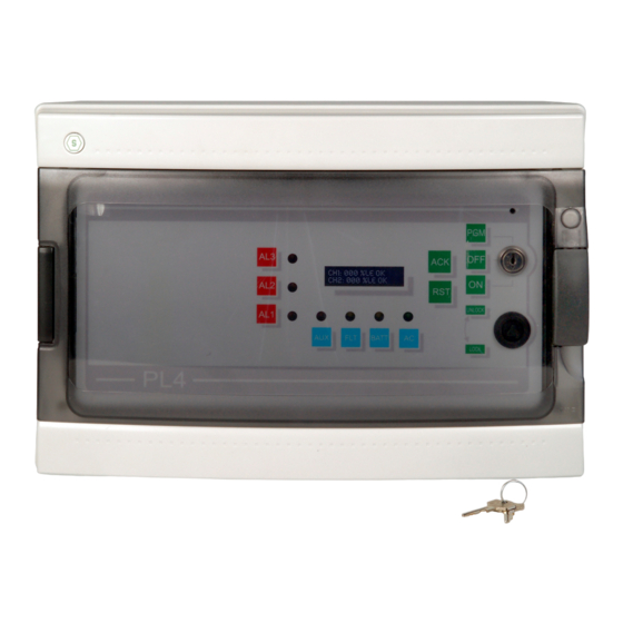
Manual de usuario e instalación / Installation and user manual PL4+ CARACTERÍSTICAS TECHNICAL TÉCNICAS SPECIFICATIONS Panel frontal 4.1 The front panel El panel frontal de la central PL4+ dispone de On the front panel, status LED's are present los siguientes leds: to indicate: (AL 1) Alarma 1... -
Page 19: Conexión De Baterías Y Primer Encendido
Manual de usuario e instalación / Installation and user manual PL4+ Conexión baterías Battery connection and first primer encendido switching on Gire la llave hasta la posición OFF y Turn the key to the OFF position and power • • conecte la central. -
Page 20: Central En Alarma
Manual de usuario e instalación / Installation and user manual PL4+ Central en alarma Alarm condition Cuando uno o más detectores sobrepasan los When one or more detectors exceed the preset umbrales, la central activa una señal acústica. thresholds, the control unit activates an acoustic El mensaje de OK en la pantalla cambia a A1, warning. -
Page 21: Deshabilitar La Central
Manual de usuario e instalación / Installation and user manual PL4+ Deshabilitar la central UNSET mode Llave en posición OFF y led de avería (FLT) KEY SWITCH in OFF position. This is the encendido. Es este estado se gestionan las UNSET mode. -
Page 22: Alarma Fuera De Rango
Manual de usuario e instalación / Installation and user manual PL4+ Alarma fuera de rango Over range alarm Cuando una señal de entrada excede el límite When an input signal is over range (input (entrada >20mA) de las activaciones normales >20mA) besides usual... - Page 23 Manual de usuario e instalación / Installation and user manual PL4+ PROGRAMACIÓN PROGRAMMING MENU Gire llave hasta posición Turn the key to PGM position and follow the (programación) y siga el diagrama que se block diagram below. muestra a continuación: MN-DT-516.doc 13/06/2017 23 de 33...
-
Page 24: Ejemplo De Programación De Una Entrada
Manual de usuario e instalación / Installation and user manual PL4+ Ejemplo de programación Example of input channel de una entrada programming Ejemplo de programación de un detector de gas Example of programming of one flammable gas inflamable (0-100% LIE). detector (0-100% LEL). - Page 25 Manual de usuario e instalación / Installation and user manual PL4+ 10%LE es un valor razonable para el primer 10% LEL is a reasonable value for the first umbral (se pueden ajustar otros valores, si fuera threshold (other values may be set, if necessary, necesario, hasta un máximo del 60%): pulse la up to the 60% of LEL): press the ACK button tecla ACK hasta que la flecha se encuentre a la...
- Page 26 Manual de usuario e instalación / Installation and user manual PL4+ Utilice la tecla RST para obtener la indicación Use RST to achieve the indication of channel 2 del cana 2 (CHN.:2) y realizar la programación (CHN.: 2) and carry out the input channel 2 del canal (entrada) 2 tal y como se ha descrito programming as previously described for para el canal 1.
-
Page 27: Programación De Entrada De Detector De Oxígeno
Manual de usuario e instalación / Installation and user manual PL4+ Programación de entrada de Oxygen detector input detector de oxígeno channel programming A continuación se detalla cómo programar la Here below details are given to program the central PL4+ cuando controla detectores de PL4+ control unit when connected to Oxygen oxígeno de 4-20mA y con rango de medición detectors. -
Page 28: Menu Tiempos
Manual de usuario e instalación / Installation and user manual PL4+ MENU TIEMPOS "TIMES” menu Programación de relés de salida Output relays programming (versión de firmware 3.0) (firmware release from 3.0 on) El modo TIEMPOS de la central PL4+ permite The TIMES mode of PL4+ control unit allows the realizar una programación personalizada de los output... -
Page 29: Rearme De Los Parámetros Por Defecto De Fábrica (Versión De Firmware 3.0)29
Manual de usuario e instalación / Installation and user manual PL4+ El segundo parámetro de TIEMPOS actúa The second “TIMES” parameter acts on the sobre el periodo de tiempo de desactivación deactivation time delay of the threshold 1 de la salida de umbral 1 que transcurre desde la output measured from the alarm off condition desactivación de la alarma (la señal del detector (the detector signal returns below the 1... - Page 30 Manual de usuario e instalación / Installation and user manual PL4+ Parámetros por defecto de fábrica Default parameter values Menú Valores por defecto Menu Default value CHN.1 NORMAL CHN.1 NORMAL RANGO 100 %LEL RANGE 100 %LEL AL.1 010 %LEL AL.1 010 %LEL AL.2 015 % LEL...
- Page 31 Manual de usuario e instalación / Installation and user manual PL4+ MN-DT-516.doc 13/06/2017 31 de 33 (MT3910.doc)
- Page 32 Manual de usuario e instalación / Installation and user manual PL4+ GARANTÍA PARA WARRANTY COUPON FOR REPARACIÓN REPAIRING La garantía de los productos de Sensitron es Warranty on Sensitron products is valid 1 year válida para un año desde la fecha de from the manufacturing date placed on the fabricación indicada en el equipo.
- Page 33 Manual de usuario e instalación / Installation and user manual PL4+ Honeywell Life Safety Iberia Teléfono: 902 03 05 45 www.honeywelllifesafety.es MN-DT-516.doc 13/06/2017 33 de 33 (MT3910.doc)
Need help?
Do you have a question about the Notifier ST.PL4+ and is the answer not in the manual?
Questions and answers