
Related Manuals for HISEER AS10/LF


Summary of Contents for HISEER AS10/LF
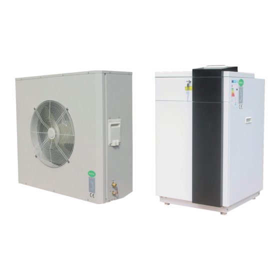
- Page 1 AIR TO WATER HEAT PUMP —— Split EVI Operation, installation &maintenance manual V.201510 The installation of this unit is to adhere to all local Building Codes and Standards...
-
Page 2: Table Of Contents
Commissioning Form............................. 42 Alarms ................................43 Maintenance ..............................46 Dimensions ..............................48 Water Pressure Plots............................49 AS10/LF ................................. 49 AS13/LF ................................. 51 Temperature and sensor resistance table ......................52 Components ..............................54 Electric wiring diagram ..........................56 Technical Specifications ..........................58... -
Page 3: Working Principle
Working principle Buffer tank ② ⑤ ① ④ ⑥ ③ Outdoor unit Indoor unit 1. The low pressure and low temperature liquid 5. The cycle repeats. refrigerant coming out of expansion valve exacts 6. When EVI condition is met, EVI expansion valve heat energy from the air through finned coil heat ⑥... -
Page 4: Nomenclature
Nomenclature AS10/LF D6NNHE B: 220V, 3~50/60Hz Air source heat pump C: 380V, 3~50Hz With Carel controller 380-400V, 3~60Hz D: 380-415V,3~50Hz 440V, 3~60Hz Rated heating output P: 208-230V, 1~60Hz Q: 220-240V, 1~50Hz L:EVI for low ambient temp. 6: 60Hz B:Standard Heating... -
Page 5: Specialist Tools
Specialist Tools Specialist tools that might be used on installation, commissioning and maintenance. The tools as exclusive tools for R410A refrigerant. 1 Gauge manifold ·Only for R410A ·Use the existing fitting specifications.(G1/4”) ·Use high-tension side pressure of 5.3MPa·G or over. 2 Charge hose ·Only for R410A ·Use pressure performance of 5.09MPa·G or over. -
Page 6: Pre-Installation
Pre-Installation Movement and Storage Note: ensure the correct refrigerant gas is used to recharge the unit as an incorrect gas can cause The unit must not be transported, moved or stored at damage beyond repair to the compressor. greater than a 30° angle from the upright position. Store the unit in a dry area until required. -
Page 7: Installation Location
Installation Location The unit must be installed on a solid level surface The unit must be installed level in both axes (less on a concrete pad foundation not connected to the than 2mm tolerance per meter) house foundation. Rubber cushions can be added to reduce vibration and noise if required. -
Page 8: Positioning
Positioning Outdoor unit 600mm 600mm Indoor unit... -
Page 9: Buffer Tank
Buffer Tank A buffer tank is recommended to ensure a trouble free Inlet water temp sensor should be taken out of the unit heat pump operation. A suitable buffer tank can avoid and put into buffer tank’s sensor pocket. The Inlet water excessive heat pump cycling (switching on and off). -
Page 10: Frost Protection
Frost Protection The plate heat exchanger, the piping and the hydraulic 1. Drain the water from the system, using the drains in pump can be damaged by frost, despite the built-in anti- the lower part of the unit. freeze protection of the unit. 2. -
Page 11: System Overview
Systems Overview Heating and Cooling ( Without internal hot water pump ,three way valve and electric heater) Buffer tank ② ⑤ ① ④ ⑥ ③ Outdoor unit Indoor unit Name Description Included ? Name Description Included ? Circulation pump External Inlet water temperature sensor Internal Electric heater... - Page 12 Systems Overview Heating Mode Working Principle: Cooling Mode Working Principle: On heating mode When the Inlet water temperature B1 ≥ RTc+ST03 (RTc is the actual read inlet water temp. of last stop), a. When SF04:enable compensation=NO, the compressor will start to cool until Outlet water When the Inlet water temperature≤...
-
Page 13: System Overview
Systems Overview Heating with hot water (with internal water pump, three way valve and electric heater ) Buffer tank Outdoor unit Indoor unit Name Description Included ? Name Description Included ? Circulation pump Internal Inlet water temperature sensor Internal Electric heater Internal Outlet water temperature sensor Internal... - Page 14 Systems Overview 1. Heating Mode Working Principle: 2. Hot water production working principle: On heating mode, Three way valve (VXV) will open On hot water mode, Three way valve (VXV) will open AB-A. AB-B. 1) When SF04 enable compensation=NO: a. When the inlet water temp. B1 ≤ RTc-ST04, (RTc When domestic hot water requirement calls, the three is the actual read inlet water temp.
-
Page 15: Installation
Installation 1. The pipe installation must adhere to the local unit from operating outside of its running parameter Building Code, standards and any local council such as control devices; shutoff valve, bleed valves, requirements. safety valves and expansion tanks. 2. Ensure that the water flow and returns are correct and 6. - Page 16 Pipe connections Connecting refrigerant pipe (not supplied) Flare connections Expansion: Install the refrigerant pipes between the outdoor unit and indoor unit. Installation must be carried out in accordance with current norms and directives. · If indoor unit is higher than outdoor unit more than 5m, an oil return curve must be made in each 5m .
- Page 17 Pipe connections Filling refrigerant: · Aim the flare connection of copper coil at the center of screw connection of heat pump , screw the flare nut as tightly as possible manually. After finishing pipe connections, pressure test ,leak test and vacuuming, the service valves can be opened. ·...
- Page 18 Electrical Connections Power Connection Before connecting the power supply, please confirm the IMPORTANT: unit suits the power supply. During the installation of the unit, first make the Breaker protection must be installed according to water connections and then electrical connections. the max value stated in the nameplate attached to If the unit is to be removed first disconnect the electrical connections, then the water connections to...
-
Page 19: Electrical Connection
Electrical connection Connecting indoor and outdoor unit Important: Temperature sensor must be separated (min 20 cm) from high voltage power cables to avoid interference which will cause read temperature Use cable (not less than 1.5m (not supplied) to fluctuating and heat pump can not work normally. connect indoor and outdoor unit via control board terminal connection . - Page 20 Electrical Connections The unit has two ways to turn ON/OFF heating B1-B2 switch is activated to turn On/Off the unit. functions. When the A/C switch B1-B2 is bridged, the unit’s SF14: A/C On/Off way 1.) remote 2.) keyboard heating function is activated. An external signal like a timer or thermostat, etc could be connected to B1-B2 to A/C Switch: activate or deactivate the unit’s heating function.
- Page 21 Electrical Connections The unit has two ways to turn ON/OFF domestic hot A1-A2 switch is activated to turn On/Off the hot water water functions. function. SF13: HW On/Off way 1.) remote 2.) keyboard hot water switch A1-A2 is bridged, the unit’s hot water function is activated.
- Page 22 Electrical Connections External Water Pump Connection Auxiliary Heating Electric Heater or (N02) Boiler (NO4) There is a connection port (1-2) at the terminal block There is a connection port (10-11) which can be used to for connecting circulation water pump. activate and de-activate an auxiliary electric heater or a boiler.
-
Page 23: User Guide
User Guide User interface User interface (Display window & button area) Find the user interface and connection cable from compressor room . Standard factory delivered connection cable is 10m. User interface should be installed indoor. It could be installed about 1.5m up from the floor ,out of reach of children. - Page 24 User Guide Symbol explanation Heating mode Domestic hot water mode + Cooling mode Cooling mode Water pump Domestic hot water mode Compressor Domestic hot water mode + Heating mode Menu Tree Code Indication Code Indication Compressor settings Setpoints Condenser settings User interface Evaporator settings Alarm settings...
- Page 25 User Guide Access Rights Three groups of users with different privilege levels are described below. Main Activities Privilege Level Special • View information and • Password required status Manufacturer • Configure and commission applications by setting/adjusting • Acknowledge warnings parameter values and alarms • Password required • Heating /Cooling...
- Page 26 User Guide Unit on/off (when unit on/off way setting press button to enter, it will display. is keyboard) Unit on/off Press button, it display AC status (heat): HW status: Unit on/off Unit A/C and DHW are successfully switched on. “Starting “ displays on screen ,water pump turns on and Press button, it display the unit current air display pump symbol on screen, with some minutes’...
- Page 27 User Guide I/O input/output Change System mode Button Operation: Prg→User→System mode This menu display the unit read temperature sensors value , digital switch on/off state, components on/off System mode only could be changed on heating/cooling state. unit (SF01 unit type setting cooling + heating). AC inlet temp When unit is off state, press “Prg”...
- Page 28 User Guide Changing Set points (for user) Display Procedures press <Prg> to main menu, press Down button to User, Press Enter button, User Press Down button to the desired parameter. Press Enter button, when 7.0 is flashing, press Up or Down button to change the value.
- Page 29 User Guide Heating compensation curve setting temperature is ST05+ST06*(ST05-OT)=20+0.7*(20-(-20))=48 ℃ ; Heating compensation curve setting User does not need to calculate it .Just check from The control temperature for heating mode has two below curves. methods: fixed and changeable temperature. The fixed There are three curves with ST05 from 18 to 22 and temperature is a fixed value and directly set by the ST06 from 0.3 to 2.
- Page 30 User Guide With the drop of the outdoor temperature, the control The calculated control water temperature will not be temperature become higher and higher to meet the large over ST14 Maximum heating temperature and will heating requirement. not be lower than ST13 With the increase of the outdoor temperature, the control Minimum heating temperature temperature become lower and lower, so that the heat...
- Page 31 User Guide Three curves of different ST05 setting: Press to menu S11: ST05=25.0℃ ST06=0.6 00.0℃ Heat setp.= 40.0℃ You could input any OT value ,press and relative heating control temp. will be calculated. If OT=-15.0 ℃ , actual control temp. is 49.0 ℃ . -15.0℃...
- Page 32 User Guide Timezone on/off Timezone on/off Monday: Copy from Monday Timezone on/off Confirm: TR09: AC timezone No TR10: HW timezone No Change Monday to Tuesday, and change “No” to “Yes” ,then Tuesday’s timezone setting will be same as Timezone activates the pre-set timer programs. Monday.
- Page 33 User Guide Important safety information for end The electrical supply must be isolated during a users heightened risk of lightning strikes. Do not attempt to move the appliance once installed; Installation and service works of the heat pump should this must be carried out by a qualified engineer. only be done by authorized installer and after sales Isolate the electrical supply to the appliance if an odour people.
-
Page 34: Service Guide
Service Guide Access Service Level Parameter data Display Procedures press <Prg> to main menu, press Down button to Parameter, Press Enter button, Enter password Press Enter and 0 will flash, press Down button to the correct figure, press 0000 Enter to confirm. Likewise, change the other 3 figure .After 4 correct figure are inputted, It will enter Service level parameter. - Page 35 Service Parameters Service Parameters: Para- Descriptions Min. Max. Unit meter fault Continuous EV01 Water pump control mode Continuous work or work by regulation work EV03 Water pump set temp. difference on cooling ℃ EV04 Water pump set temp. difference on heating ℃...
- Page 36 Service Guide Steps to open the cabinets: 3. The right panel could be removed as the same way of removing the left panel. The panels must be removed as the order : front 4. Unscrew the screws as below and then back panel panel –...
- Page 37 Service Guide Control process Cooling demand Turn on process at heating mode 1.) Start water pump , check water flow switch 2.) 5 seconds after water flow switch closes, if there is heating demand, start fan and compressor Turn off process at heating mode 1.) Switch off compressor 2.) After 5 second’s delay, switch off fan motor 3.) After 30 seconds’...
- Page 38 Service Guide Hot water priority: Crankcase heater running control (N05) When all of conditions below are met, compressor · When unit is heating, if there is a call for hot water crankcase heater is switched on , it start 3 way valve at once and turn to hot water 1.) Compressor is OFF ;...
- Page 39 Service Guide The EC fan running control (Y1) Heating and DHW mode,ambient temperature≤CN07,fan runs as CN02, ambient temperature≥CN08 , fan runs as On cooling mode, ambient temperature≥CN05 , fan CN03, CN07 < ambient temperature < CN08 , fan runs runs as CN01, ambient temperature≤CN06 , fan runs as on the speed proportionally between CN03 and CN02.
- Page 40 Service Guide The pump PWM running control (Y3) Defrosting control On cooling mode, when compressor is on, pump PWM The unit is equipped with hot gas defrosting. When runs as EV05 for 3 minutes, then runs with ( Inlet the conditions of defrosting are met, the fan stops, the temperature-Outlet temperature ) =EV03 as target via 4 way valve changes direction and the hot gas flows PID control .
- Page 41 Manufacturer parameters Access Manufacturer Level Parameter data Display Procedures press <Prg> to main menu, press Down button to Parameter, Press Enter button, Enter password Press Enter and 0 will flash, press Down button to the correct figure, press 0000 Enter to confirm. Likewise, change the other 3 figure .After 4 correct figure are inputted, It will enter Service level parameter.
- Page 42 Manufacturer parameters Parameter Descriptions Default Min. Max. Unit CM01 Compressor minimum ON time Sec. CM02 Compressor minimum OFF time 1000 Sec. CN01 EC fan Max. speed (cooling) 4.0 (10KW) CN02 EC fan Max. speed (heating) 4.2 (13KW) CN03 EC fan Min.. speed CN04 EC fan Max speed (night mode) CN05...
-
Page 43: Commissioning And Adjusting
Commissioning and Adjusting Preparations- Filling and Flushing The temperature difference between ST/RT can be adjusted by increasing the flow rate by either using 1. Before commissioning, ensure the whole system has circulation pumps or control valve. been properly flushed and filled with water. Air in the System after Startup 2. -
Page 44: Commissioning Form
Commissioning Form Client / Installation address: Telephone Number Installer: Commissioned by Heat pump Model: Heat pump serial number: Commissioning date: The heating system has been filled and pressure tested YES ( Expansion vessel for heating is sized, fitted & charged in accordance with manufacturer’s YES ( instructions The heat pump is fitted on a solid/stable surface capable of taking its weight... -
Page 45: Alarms
Alarms The alarms are divided into two groups: auto reset 5. Ensure that the fault has been fixed before the alarm has been reset. alarms and manual reset alarms. When an alarm is detected: 1. Auto reset alarm, the user is not required to acknowledge and reset it. - Page 46 Alarms Viewing Alarm history High outlet water temperature protection (Code: AL05) If ST≥AR03, the compressor is off ,after 5 seconds delay, the fan motor will be stopped, PWM water pump Display Procedures will run as EV05,other parts will keep its original state. Press <Prg>...
- Page 47 Alarms other parts will keep its original state. A continuous Anti-freeze protection (Code : AL26) blink code AL35 will appear on the LCD, until When water pump is off and ambient temperature ≤ SF06, B11(LPS)≥AR13+AR14, the unit will turn to its normal water pump will be switched on in every AR11 interval work.
- Page 48 Alarms Compressor overload (code: AL24) Phase relay protection (Code : AL23) There is a phase relay for three phase units. If AL24 alarm is activated, open the control he control box panel to find the thermal overload load If AL23 alarm is activated, open the control relay and press 'RESET".
-
Page 49: Maintenance
Maintenance To ensure the optimal performance of the unit regular exchanger water inlet and outlet temperature maintenance is essential. Failure to undertake regular G. Actual liquid sub-cooling, overheating at the maintenance can reduce the unit performance and of the expansion device on heat pumps verify correct system shorten the life of the unit . - Page 50 Alarms Verify the Alarm Status Water Circuit Checks 1. Check the alarm menu when the unit is in the 1. Clean the water filter if fitted. standby mode to see if any alarms or warning have 2. Purge the system to remove any air. occurred.
-
Page 51: Dimensions
Dimensions AS10/LF AS13/LF Indoor unit Outdoor unit 1050... -
Page 52: Water Pressure Plots
Water Pressure Plots AS10/LF m3/h Optional water pump 1 curve (AS10/LF ) UPM2K 25-60 130, 1×230V, 50/60 Hz... - Page 53 Water Pressure Plots Optional water pump 2 curve (AS10/LF) UPM3 FLEX AS 25-70 130...
-
Page 54: As13/Lf
Water Pressure Plots AS13/LF m3/h Optional water pump curve (AS13/LF) UPML 25-105 130 PWM, 1×230V, 50/60Hz... -
Page 55: Temperature And Sensor Resistance Table
Temperature and sensor resistance table Except B5PT sensor, other temperature sensors from B1 to B8 is NTC10K NTC10K@25 ℃ β 3435 resistant resistant resistant Temp. Temp. Temp. Max. standard Min. Max. standard Min. Max. standard Min. kΩ kΩ kΩ kΩ kΩ... - Page 56 Temperature and sensor resistance table B5 PT is NTC 50K sensor NTC 50K@25 ℃ β 3977 Temp. -resistant Temp. resistant Min. Max. % tolerance ℃ tolerance kΩ %/℃ kΩ kΩ Min. Max. Min. Max. ℃ 1630.77 -6.623 1559.17 1705.49 -4.39 4.58 0.66 -0.69...
-
Page 57: Components
Components Low pressure transducer Four way valve High pressure transducer Service connection (HP) Electric heater backup Expansion tank 3 way valve Circulation pump Main circuit Expansion valve Gas-liquid separator EVI Expansion valve Economizer Plate heat exchanger Service connection (LP) Compressor Liquid receiver... - Page 58 Components 18. Finned coil heat exchanger 19. Fan blade 20. EC Fan motor 21. EC fan motor board 22. Grill 23. De-icing heater 24. Terminal block 25. Pump relay 26. Transformer 27. Carel controller 28. User interface 29. Compressor contactor 30.
-
Page 59: Electric Wiring Diagram
Electric wiring diagram Indoor unit... - Page 60 Electric wiring diagram Outdoor unit WIRING DIAGRAM OFAN MODEL AS13/LF(W) TO INDOOR UNIT The components within the dotted lines are optional parts.
- Page 61 Model Number AS10/LF AS13/LF Heat output/Power consumption at A7/W35℃ 10.11/2.40 14.68/3.60 COP at A7/W35℃ 4.21 4.08 Heat output/Power consumption at A2/W35℃ 7.65/2.33 11.60/3.43 COP at A2/W35℃ 3.28 3.38 Heat output/Power consumption at A-7/W35℃ 6.52/2.52 8.4/3.15 COP at A-7/W35℃...
Need help?
Do you have a question about the AS10/LF and is the answer not in the manual?
Questions and answers