
Related Manuals for HISEER GSWW60


Summary of Contents for HISEER GSWW60
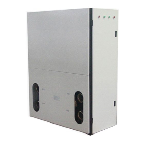
- Page 1 GEOTHERMAL HEAT PUMP Installation ,Operation &Maintenance Manual The Installation of this unit is to adhere to all Local Building Codes and Standards...
-
Page 2: Pre-Installation
Pre-Installation Pre-Installation Important Site Instructions The installation, commissioning, inspection, maintenance and repairs must only be carried out by a qualified person. All electrical wiring must be completed by a licensed electrical contractor in accordance with the appropriate standards. The drilling work requires a permit from your local council. The heating system and heat source must be properly designed and dimensioned to ensure an efficient operation. -
Page 3: Installation Location And Positioning
Installation Location and Positioning Installation Location and Positioning The unit must be installed in a protected area that is free from rain and water penetration. The unit must be installed on a solid level surface, preferably on a concrete pad not connected to the main house slab foundation. -
Page 4: Buffer Tank
Buffer Tank Buffer Tank A buffer tank is recommended to ensure a trouble free heat pump operation. A suitable buffer tank can avoid excessive heat pump cycling (switching on and off). The buffer tank provides a hydraulic separation from the volume flow in the heat pump and heating circuits. - Page 5 Systems Overview (Outdoor side) System Overview Vertical Ground Loop System Name Description Location Name Description Location Outdoor side water Outdoor temperature External Internal pump sensor Safety valve External Particle filter External Brine tank/expansion External tank...
- Page 6 Systems Overview (Outdoor side) System Overview Horizontal Ground Loop System Name Description Location Name Description Location Outdoor side water Outdoor temperature External Internal pump sensor Safety valve External Particle filter External Brine tank/expansion External tank...
-
Page 7: System Overview Ground Water With Intermediate Heat Exchanger System
Systems Overview (Outdoor side) System Overview Ground Water with Intermediate Heat Exchanger System Name Description Location Name Description Location Outdoor temperature Outdoor side water pump External Internal sensor Ground water pump External Particle filter External Brine tank/expansion External Safety valve External tank Water flow switch... - Page 8 Systems Overview (Indoor side) Several units could be connected together to build a large system. Each controller is set to different cooling, heating set point (2-3 degree difference)so they will not start at the same time to reduce start current. All units water pump control signal connected together to A/C contactor which supply power for water pump so the water pump can run as long as any unit is running.
- Page 9 Systems Overview (Indoor side) Heating working principle: To set two units in parallel operation, set the primary unit to the required parameters, unit two is to have 3~5°C difference of ST01,ST02 and ST05 to allow for energy stage control. Switch on both units’ A/C switches one by one, if the RT parameter is lower than the set values of both units, then the units will start to heat together.
-
Page 10: Installation
Installation Installation Installation must be carried out in accordance with current Standards and Building Codes . T he heat pump does not come fitted with shutoff valves and these must be fitted outside of the heat pump to facilitate future service .... - Page 11 Installation Where there is more than one ground loop these must be connected in parallel with a means of adjusting the flow. For surface soil heat, the pipe should be buried at a depth of about 1.8 meters and the distance between the hoses should be at least 1 meter. For bore holes the distance between the holes must be at least 15m.
-
Page 12: Electrical Connection
Electrical Connection Electrical Connection G0 PE D1 M D4 D5 X1 GND +24V SIEMENS RWR470.10 RS485 RJ45 Q13 Q14 Q44 Q54 Q64 Q23 Q74 Q84 Y1 G0 Y2 B- GND Terminal Assigments Terminal Assignments Power supply AC/DC 24 V Supply 1 (AC 24 V 230 V) Power supply ground Compressor 1... -
Page 13: Power Connection
Electrical Connection Power Connection: Before connecting the power supply please confirm the unit suits the power supply as unit nameplate. Breaker protection must be installed according to the max value stated in the nameplate attached to the unit inside of front panel. The equipment must be installed via an isolator switch with a minimum breaking gap of 3 mm .... -
Page 14: Outdoor Ambient Temperature Sensor
Electrical Connection Outdoor Ambient Temperature Sensor: The outdoor temperature sensor (OT) is a standard part placed inside the electric box. One terminal is connected with the PC board X3 and GND, the other terminal must be installed outdoors. It should be mounted on a wall that has the mean outdoor temperature which can accurately measure the outdoor temperature and not to be exposed the rain, sun and snow. - Page 15 Electrical Connection Outdoor Side Water Pump: Outdoor side water pump is connected to terminal port (1-2). If the water pump current is over 2A, an A/C contactor must be used to activate the water pump. Indoor Side Water Pump: Indoor side water pump is connected to terminal port (3-4). If the water pump current is over 2A, an A/C contactor must be used to activate the water pump.
-
Page 16: Electric Heater
Electrical Connection Electric Heater: Electric heater is connected to terminal port (10-11). An A/C contactor must be used to activate the electric heater. A thermostat T should be attached on the outer container of heater to prevent heater from overheating. (Triple phase) K M 2 2 2 2 Hot Water Pump or Three Way Valve:... - Page 17 Electrical Connection A/C Switch: The unit’s A/C ON/OFF cannot be operated by any button on the controller. When the A/C’s switch B1-B2 is bridged, the unit’s heating /cooling function is activated. An external signal like a timer or thermostat, etc could be connected to B1-B2 to activate or deactivate the unit’s heating /cooling function.
- Page 18 Electrical Connection Alarm Unit’s Output: When any alarm occurs Terminal port (5-6) will have a 230V output. It could be connected to an alarm unit (such as indication lighter, alarm bell etc).
- Page 19 Controller Controller Controller Display (Display window & button area) Display Area : In normal working mode: display 1 shows a parameter code, display 2 shows this code temperature value. In parameter setting mode: display 1 shows parameter code, display 2 shows this parameter value. Menus area :...
- Page 20 Controller Symbol explanation Cooling mode Heating mode Power Hot water mode Indoor side water pump Compressor energy grade Compressor Water flow switch (light on represents the water flow switch alarm) Outdoor side water pump...
-
Page 21: Viewing Temperature
Controller Selection of System Modes Display Procedures In the stop mode (A/C switch and hot water switch are OFF), press the <Plus> button for 2 seconds, and release it to activate the selection of system mode. The current system mode will start flashing. -
Page 22: Changing Set Points
Controller Changing Set Points Display Procedures In stop mode, press <Enter> for 2 seconds and release it to activate the Menu mode. When the icon is blinking, press <Plus> or <Minus> to navigate to the menu, and then press <Enter> to proceed. Contents under the Parameter Menu may vary with the privilege right of the user. -
Page 23: Adjusting Parameter Values
Controller Adjusting Parameter Values Display Procedures After inputting password and enter into the parameter setting mode. Press <Plus> or <Minus> to select the parameter code, and press <Enter> to confirm. The default value of the parameter will start flashing, allowing you to make a change. - Page 24 Controller Heating compensation curve setting The control temperature for heating mode has two methods: fixed and changeable temperature. The fixed temperature is a fixed value and directly set by the user from the set area. The changeable temperature is determined by values of ST05, ST06 and the actual outdoor temperature measured by the OT sensor probe.
- Page 25 Controller Three curves of different ST05 setting:...
- Page 26 Controller Outdoor Side Anti-Freezing Setting Ground water with immediate heat exchanger system AR11 (outdoor side low outlet water temperature protection), factory default setting is 5 ℃ AR08 (low evaporator temperature protection), factory default setting is -2 ℃ Ground loop system If brine is adopted as an outdoor side heating medium, AR11 needs to be changed according to brine freezing point.
-
Page 27: Commissioning And Adjusting
Commissioning and Adjusting Commissioning and Adjusting Switch Off /Disconnect the Mains Fuse Check Refrigerant Circuit for Leaks. Check heat pump gas pressure gauge reading for any leak. Open the front door with the key. Check the heat pump interior with a refrigerant leak detector or leak detection spray for refrigerant leaks. - Page 28 Commissioning and Adjusting Checking the Tightness of Electrical Connections Checking the Input Terminals and Contactors Check the voltage and cycle at the mains connection, at the inlet terminals and at the contactors. Interchange phases L1 and L3, if the phase sequence protector red light illuminates. Checking the Sensor Connections Check whether all sensors have been connected correctly.
-
Page 29: Checking The Refrigerant Circuit
Commissioning and Adjusting Checking the Refrigerant Circuit Observe the sight glass in refrigerant circuit. Bubbles >5 mm should not be visible, when heating flow has stabilized at 35°C. If large bubbles are visible, search and repair the leak in respective stage and refill with refrigerant. -
Page 30: Warning And Alarm
Warning and Alarm Warning and alarm Warning Management When a warning is detected, the corresponding warning code will be displayed on the LCD. The warning icon will flash simultaneously. Only the latest 10 warnings will be kept under the menu. Upon power failure of the controller, the warning logs will be erased and recounted Codes Meaning... - Page 31 Warning and Alarm Alarm Management The alarms in RWR470.10 are divided into two groups: auto reset alarms and manual reset alarms. Auto reset alarm, the user is not required to acknowledge and reset it. The corresponding device will be automatically restarted once the alarm status disappears. Once a manual reset alarm is detected, the system will be stopped automatically.
- Page 32 Warning and Alarm Auto Reset Alarms The following are codes for auto reset alarms with their meanings. Codes Meaning AL01 Compressor low pressure (D2) AL02 Compressor high pressure (D3) Low indoor side outlet water temperature protection (when ST ≤ AR01 in any AL03 mode) Low outdoor side outlet water temperature protection (when STo ≤...
- Page 33 Warning and Alarm Viewing Alarm Logs MR01 and AR01 are respectively the latest information of the manual reset alarm and auto reset alarm. Display Procedures Press down the <Enter> for 2 seconds, and release it to activate the Menu mode. Press <Plus>...
-
Page 34: Troubleshooting
Trouble shooting Trouble Shooting Description Possible cause Check Check the mains supply phases and faulty or disconnected fuse active/replace fuse Power failure Mains fault, voltage notify your electricity supplier fluctuations wrong phase sequence check phase sequence protector Check thermal relay and active/re Thermal relay has tripped set thermal relay Compressor... -
Page 35: Maintenance
Maintenance Maintenance To prevent faults due to sediment in the heat exchangers, care must be taken to ensure that no impurities can enter either the heat source system or the heating system. In the event that operating malfunctions due to contamination occur nevertheless the system should be cleaned as described below. - Page 36 Dimension Dimension...
- Page 37 Pressure drop curve Pressure Drop Curve m 3/ h...
-
Page 38: Technical Specifications
Technical specifications Technical specifications Heat pump Type GSWW60 Dimensions,weights,connection dimensions Dimensions HxWxD 1620x550X1250 Weight Refrigerant Type R407C Filling weight Permissible operating pressure Pipe connector-hot side Inch G4” Pipe connector-cold side Inch G4” Evaporator Type Brazed plate heat exchanger Condenser Type... -
Page 39: Electric Wiring Diagram
Electric wiring diagram Electric wiring diagram ( 7 、 I n c o m i n g s u p p l y 3 x 4 0 0 V N L 3 L 2 : ( 1 、 、 C O M P R E S S E R I n d o o r f l o w s w i t c h O u t d o o r f l o w s w i t c h I N D O O R...
Need help?
Do you have a question about the GSWW60 and is the answer not in the manual?
Questions and answers