Table of Contents
Advertisement
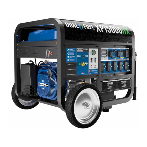
XP15000HX
U
S
E
R
M
A
N
U A
L
5800 Ontario Mills Pkwy
REV: XP15000HX-09082022
Ontario, CA 91764 USA
This manual provides information regarding the
www.duromaxpower.com
operation and maintenance of these products. We
have made every effort to ensure the accuracy of the
Call our Customer Care Team Toll Free 8-5pm PST Mon-Fri
information in this manual. We reserve the right to
844-DUROMAX
change this product at any time without prior notice.
Advertisement
Table of Contents
Troubleshooting

Subscribe to Our Youtube Channel
Related Manuals for DUROMAX XP15000HX


Summary of Contents for DUROMAX XP15000HX
- Page 1 XP15000HX 5800 Ontario Mills Pkwy REV: XP15000HX-09082022 Ontario, CA 91764 USA This manual provides information regarding the www.duromaxpower.com operation and maintenance of these products. We have made every effort to ensure the accuracy of the Call our Customer Care Team Toll Free 8-5pm PST Mon-Fri information in this manual.
-
Page 3: Table Of Contents
CONTENTS Introduction Introduction ........................6 General Safety Procedures ................... 8 Carbon Monoxide Safety ..................... 12 Unit and Purchase Information .................. 14 Generator Components Generator Components ....................16 Package Contents ......................18 Generator Setup Unpack the Generator ....................21 Wheel Kit Installation ....................22 Connect the Battery .................... - Page 4 CONTENTS Maintenance and Care Maintenance Schedule ....................54 Break-In Period ......................55 Maintenance Log ......................55 Checking the Oil ......................56 Changing the Oil ......................57 Cleaning the Air Filter ....................58 Spark Plug Maintenance ....................60 Emptying the Gas Tank ....................62 Transporting the Generator ..................
- Page 6 DUROMAX The DuroMax Way is more than just a brand, it is our understanding and appreciation of just how important power can be to someone without it… DUROMAX FOR HOME DUROMAX FOR WORK DUROMAX FOR PLAY Electricity in our home not...
-
Page 7: Introduction
INTRODUCTION DuroMax Power Equipment is headquartered in Ontario, California and is the industry’s leader in Dual Fuel portable generator technology. In addition to a full assortment of portable generators ranging from digital inverters to large 15,000-watt portable standby units, their product line includes pressure washers, engines, pumps, and accessories. -
Page 8: General Safety Procedures
GENERAL SAFETY PROCEDURES SAFETY ALERT SYMBOL The safety alert symbol is used with one of the safety words (DANGER, WARNING, or CAUTION) to alert you of hazards. Please pay attention to these hazard notices both in this manual and on the engine. Please familiarize yourself with the following safety symbols and words: ●... - Page 9 WARNING: This generator may emit highly flammable and explosive gasoline vapors, which can cause severe burns or even death. A nearby open flame can lead to an explosion even if not directly in contact with gasoline. ● Do not operate near an open flame. ●...
- Page 10 GENERAL SAFETY PROCEDURES In addition to the above safety notices, please familiarize yourself with the safety and hazard markings on the generator. DANGER DO NOT OVERFILL 1.5” THE GAS TANK OVERFILLING CAN RESULT IN A FIRE, EXPLOSION, OR DEATH.
- Page 11 CAUTION HIGH TEMPERATURE DON’T TOUCH HOT EXHAUST DANGER KEEP SAFE DISTANCE BURN RISK CARBON MONOXIDE SAFE DISTANCE DON’T TOUCH...
-
Page 12: Carbon Monoxide Safety
“the silent killer.” CO-ALERT Description The DuroMax CO-ALERT system was created to protect our customers and their families from dangerous carbon monoxide. Just like the detector for your home the CO- ALERT tests the air for to keep you safe and healthy. - Page 13 As the only safe way to use a portable generator, taking your generator outside is absolutely mandatory to keep your family safe from carbon monoxide. But there’s even more you can do. By educating yourself about all carbon monoxide risks, you’ll be better prepared to protect your family from this colorless, odorless threat.
-
Page 14: Unit And Purchase Information
UNIT AND PURCHASE INFORMATION Serial Number Serial number The serial number is located on the engine block, above and to the left of the oil fill. Serial number format The serial number will be shown in two parts. The engine model, followed by the serial number. - Page 15 GENERATOR COMPONENTS To help you get familiar with your new DuroMax generator, please see this component section for easy reference on all the generator’s individual features.
-
Page 16: Generator Components
3. Fuel Valve - ON/OFF valve that allows gasoline to the fuel switch. 4. Fuel Tank - All metal 13.2 gallon gasoline fuel tank. 5. Handles - Longest handles of any DuroMax model allow easy movement across any surface. 6. Battery - 12V DC battery that powers the electric start system. - Page 17 14. 240V 30A Outlet 9. Engine Switch 13. 30A Circuit Breaker 15. Main Breaker 12. 120V 30A Outlet 16. 50A Outlet 11. Multimeter 8. Propane Inlet 10. Idle Control 17. Propane Indicator 21. Charging Light 18. CO-ALERT 20. Battery Switch 19.
-
Page 18: Package Contents
PACKAGE CONTENTS Your generator comes with the items listed below. Please check to see that all of the following items are included with your generator. Double-Sided Spanner Spark Plug Wrench Screw Driver Phillips and slot blade Assorted wrenches used in Used in spark plug screwdriver used for generator generator maintenance and... -
Page 19: Generator Setup
GENERATOR SETUP Proper setup of your generator will get you going as soon as possible while making sure you and your equipment are safe and cared for. -
Page 21: Unpack The Generator
GENERATOR SETUP Step 1 - Unpack the Generator Unpack Cut the strapping on the box Slide the top of the box off the generator. Continue with the following steps before taking the generator off the pallet. -
Page 22: Wheel Kit Installation
GENERATOR SETUP (CONTINUED) Step 2 - Wheel Kit Installation (Optional) Install axle Insert axle bolt through frame. Install axle pin Secure axles to frame with retaining pins. Secure wheels with retaining pins. Install wheel washers Place one of the washers onto each of the axles. Install wheel and washer Place the wheels onto the axles. - Page 23 Install cotter pins Place the cotter pin through the hole at the end of each axle to secure the wheels. Install support legs Secure the support legs to the frame with the provided lock nuts. Install handles Attach the handles to the brackets on the frame using the provided bolts and nuts.
-
Page 24: Connect The Battery
GENERATOR SETUP (CONTINUED) Step 3 - Connect the Battery Remove the battery cover Remove the battery cover plate using the wrench from the toolkit. Locate the negative cable Locate the negative battery cable above and behind the battery. One side is connected to ground and the other end needs to be connected to the battery. -
Page 25: Adding Oil
. You must add the proper amount of oil before operating the generator for the first time. This amount is equal to the oil capacity of the engine crankcase: Model Number XP15000HX Engine Oil Capacity 50.7 fl. oz (1.5 L) WARNING: Do not apply engine oils with additives or 2-stroke gasoline engine oils;... -
Page 26: Adding Gasoline
Replace fuel cap and wipe up any spilled gasoline with a dry cloth. Model Number XP15000HX Gas Tank Capacity 13.2 US gal. (50 L) DANGER DO NOT OVERFILL 1.5”... -
Page 27: Grounding The Generator
Step 6 - Grounding the Generator Attach grounding wire Ground the generator by tightening the grounding nut against a grounding wire. Connect the other end to a copper or brass grounding rod that’s driven into the earth. A generally acceptable grounding wire is a No. 12 AWG (American Wire Gauge) stranded copper wire. -
Page 28: Attach Propane Inlet
GENERATOR SETUP (CONTINUED) Step 7 - Attach Propane Inlet Attach propane Inlet Remove the shipping cap from the inlet port in the center of the left hand panel. Use Teflon pipe tape around the threads of the propane inlet adapter. Securely thread the included propane inlet adapter. -
Page 29: Starting The Generator
STARTING THE GENERATOR If this is not your first time using the generator there are still steps you should take to prepare it for operation each time you use it. IMPORTANT: At this point you should be familiar with the procedures described in the first portion of this section entitled “GENERATOR SETUP”... -
Page 30: Checking The Oil
(see “Adding Oil” portion of the “Maintenance” section). Be sure to replace the cap when finished checking oil. Model Number XP15000HX Engine Oil Capacity 50.7 fl. oz (1.5 L) -
Page 31: Check The Gas Level
Step 2 - Check the Gas Level (Optional) Check fuel level If running the engine on gasoline check to see that there is sufficient gasoline in the fuel tank. The fuel gauge on top of the tank will give a rough estimate of the gasoline level. The gauge will appear white then fill red as the tank is filled. -
Page 32: Starting The Generator Using Gasoline
STARTING THE GENERATOR Starting the Generator Using Gasoline Shut main breaker OFF The breaker is located on the right side of the front power panel. Flip the breaker down to prevent accidental load when starting the generator. Turn gas valve ON The gas valve is located above the recoil starter. - Page 33 Start the generator The push-button start is located on the left side panel. Press the button for 2 seconds and release to start the generator. Turn breaker ON/ Connect The breaker is located on the right side of the front power panel.
-
Page 34: Starting The Generator Using Propane
STARTING THE GENERATOR (CONTINUED) Starting the Generator Using Propane Shut main breaker OFF The breaker is located on the right side of the front power panel. Flip the breaker down to prevent accidental load when starting the generator. Turn gas valve OFF The gas valve is located above the recoil starter. - Page 35 Turn battery switch ON The battery switch is located below the start button on the generator panel. Turn the switch “ON” to allow power to the push-button start. Turn idle control OFF The idle control is located below the start button on the generator panel.
- Page 36 STARTING THE GENERATOR (CONTINUED) Starting the Generator Using Propane WARNING: WHEN USING THE GENERATOR WITH LPG, MAKE SURE THERE IS NO POSSIBLE IGNITION SOURCE CLOSE TO THE GENERATOR. 1. Before using, make sure all of the LPG connectors and hoses are well connected and sealed.
-
Page 38: Starting The Generator Using Recoil Start
STARTING THE GENERATOR (CONTINUED) Starting the Generator Using Recoil Start Shut main breaker OFF The breaker is located on the right side of the front power panel. Flip the breaker down to prevent accidental load when starting the generator. Select your fuel If using gasoline, see step 2 on pg. - Page 39 Close choke The choke lever is located above the air filter to the left of the recoil start. Slide the lever to the right to cut the air supply and allow more gas into the engine to start. Pull the recoil start The recoil start is located on the left side panel next to the air filter.
-
Page 40: Starting The Generator Using Remote Start
STARTING THE GENERATOR (CONTINUED) Starting the Generator Using Remote Start Shut breaker OFF The breaker is located on the right side of the front power panel. Flip the breaker down to prevent accidental load when starting the generator. Select your fuel If using gasoline, see step 2 on pg. - Page 41 Push the start button The remote start has two buttons: start and stop. Press the start button two times in succession to start the generator. Turn breaker ON/ Connect The breaker is located on the right side of the front power panel.
-
Page 43: Using The Generator
USING THE GENERATOR If this is not your first time using the generator there are still steps you should take to prepare it for operation each time you use it. IMPORTANT: At this point you should be familiar with the procedures described in the first portion of this section entitled “GENERATOR SETUP”... -
Page 44: Ac Usage
USING THE GENERATOR AC Usage ● You may connect electrical devices running on AC current according to their wattage requirements. ● The chart below shows the rated and surge wattage of your generator according to its model number. ● The rated wattage corresponds to the maximum wattage the generator can output on a continuous basis. - Page 45 Tool or Appliance Rated (Running) Watts Additional Surge Watts Electric water heater (40 gal) 4000 Hot plate 2500 Radial arm saw 2000 2000 Electric stove 1500 Circular saw 1500 1500 Air compressor (1 HP) 1500 3000 Window air conditioner 1200 1800 Miter saw 1200...
-
Page 47: Connecting The Generator To A Home
Connecting the Generator to a Home Extension cords ● The most straightforward and affordable option. ● Zero commitment, no installation needed: Simply plug in your appliances and go! ● Perfect for renters, RV/camping trips, and power on the job-site. Transfer switch ●... -
Page 48: Connecting A Load To The Generator
USING THE GENERATOR (CONTINUED) Connecting a Load to the Generator NOTE: Be sure to attach devices to the correct receptacle (outlet). 120V devices can be directly connected to the 120V ONLY receptacles. ● ● 120V devices can be connected to the 120/240V receptacle using an appropriate adapter. ●... -
Page 49: Choosing The Right Power Cord
*Gauge based on twisted copper wire From home back up to just running your electric edger and everything in-between DuroMax has the power cord for you. All DuroMax cords are 100% twisted copper wire for maximum life and reliability. 120V 15A... -
Page 50: Using The Digital Multimeter
USING THE GENERATOR (CONTINUED) Using the Digital Multimeter 1. Gas Gauge 2. Load Gauge 3. V/F/T Display 1. Gas Gauge – The gasoline fuel level in the fuel tank is shown on the left side of the control center. 2. Load Gauge – The amount of power currently being used is shown on the right hand side of the control center. -
Page 51: Idle Control Usage
Idle Control Usage Idle control The idle control feature lowers the RPM of the generator when there is no load to save gas and decrease engine noise. When a load is applied, the engine will resume normal speed to provide usable power. Turn on the idle control when using intermittent loads like power tools and air compressors. -
Page 53: Maintenance And Care
MAINTENANCE AND CARE Proper maintenance and storage of your generator is essential to ensure trouble free use of your generator when you need it. By following the maintenance and care requirements, you can keep your generator running smooth and efficient for years to come. -
Page 54: Maintenance Schedule
MAINTENANCE AND CARE Proper routine maintenance of your generator is essential for safe, economical, and trouble-free operation. It will also help reduce air pollution. WARNING: Improper maintenance, or failure to correct a problem before operation, can cause a malfunction in which you can be seriously injured or killed. Always follow the inspection, maintenance recommendations, and schedules in this instruction manual. -
Page 55: Break-In Period
Break-In Period As the best practice for any new combustion motor it’s recommended to perform the break in procedure as follows: ● Run the generator for the first 6-8 hours on conventional oil, then change the oil. After the break-in period synthetic oil may be used. ●... -
Page 56: Checking The Oil
(see “Adding Oil” portion of the “Maintenance” section). Be sure to replace the cap when finished checking oil. Model Number XP15000HX Engine Oil Capacity 50.7 fl. oz (1.5 L) -
Page 57: Changing The Oil
Changing the Oil CAUTION: Worn out or dirty oil does not cool the generator properly and can lead to catastrophic engine damage. In addition to regular oil changes, it is necessary to drain the oil from the crankcase if it has become contaminated with water or dirt. -
Page 58: Cleaning The Air Filter
MAINTENANCE AND CARE (CONTINUED) Cleaning the Air Filter Routine maintenance of the air cleaner helps maintain proper airflow to the carburetor. Check that the air cleaner is free of excessive dirt after every use. CAUTION: Improper maintenance may cause less air to enter the engine or dirty air to enter the engine causing overheating and engine wear. - Page 59 Wash cleaner element Wash the sponge-like elements in household dish detergent and warm water. Dry cleaner element Pat dry on a dry cloth and allow the elements to dry completely. Add engine oil to elements Soak the dry elements in a small amount of engine oil. Ring out any excess oil.
-
Page 60: Spark Plug Maintenance
MAINTENANCE AND CARE (CONTINUED) Spark Plug Maintenance The spark plug is important for proper engine operation. SPARK PLUG A good spark plug should be intact, free of deposits, and CONSULT MANUAL properly gapped. BEFORE REMOVING CAUTION: Improper maintenance may cause reduced fuel economy, misfires, trouble starting, or damage to the spark plug threads. - Page 61 Measure plug gap Measure the plug gap with a gauge. The gap should be 0.7-0.8 mm (0.028-0.031 in). Clean and re-gap If you are re-using the spark plug, use a wire brush to clean any dirt from around the spark plug base and then re-gap the spark plug.
-
Page 62: Emptying The Gas Tank
MAINTENANCE AND CARE (CONTINUED) Emptying the Gas Tank If you have been using gasoline in your generator, before storing your generator for extended periods of time you should drain your generator fuel tank of gasoline. CAUTION: Do not store fuel from one season to another. - Page 63 Turn fuel valve ON and drain Turn the fuel valve to “ON” and allow gasoline to drain into the container until the gas tank is empty. Shut fuel valve OFF Once the gasoline is fully drained, move the fuel valve back to the “OFF”...
-
Page 65: Transporting The Generator
MAINTENANCE AND CARE (CONTINUED) Transporting the Generator Empty the gas tank Fully drain your gas tank as shown in “Emptying the Gas Tank” on page 62-63. Disconnect the spark plug cap Pull on spark plug cap to disconnect spark plug from ignition wire. -
Page 66: Storing The Generator For Same Day Use
MAINTENANCE AND CARE (CONTINUED) Storing the Generator for Same Day Use Turn the main breaker OFF Move the main breaker to the “OFF” position. Run the generator Allow the generator to run for 3-5 minutes. Turn the generator OFF Hold the start button for 2 seconds to shut off the generator. Turn battery switch OFF/ Store Turn the battery switch to the “OFF”... -
Page 67: Storing The Generator For Use Within 30 Days
Storing the Generator for Use Within 30 Days Turn breaker OFF and run Follow steps 1 and 2 as shown on “Storing the Generator For Same Day Use” on page 66. Shut fuel valve OFF and run dry Shut the fuel valve “OFF” and allow generator to run until it stalls out. -
Page 68: Storing The Generator For Longer Than 30 Days
MAINTENANCE AND CARE (CONTINUED) Storing the Generator for Longer Than 30 Days Turn breaker OFF and run Follow steps 1 and 2 as shown on “Storing the Generator For Same Day Use” on page 66. Shut fuel valve OFF and run dry Shut the fuel valve “OFF”... - Page 69 Drain the carburetor Remove drain bolt from carburetor and drain small amount of fuel in carburetor bowl. Remove spark plug Remove spark plug as shown in “Spark Plug Maintenance” on page 60. Add oil to cylinder Add 2 tablespoons of 10W-30 motor oil directly into the spark plug hole, and pull the recoil to lubricate cylinder.
-
Page 70: Specifications
SPECIFICATIONS Model Number XP15000HX AC Rated Wattage (Gasoline) 12,000 W AC Rated Wattage (Propane) 11,400 W AC Surge Wattage (Gasoline) 15,000 W AC Surge Wattage (Propane) 14,250 W AC Rated Voltage 120/240V Dimensions 40”L x 28”W x 29”H Weight 388 lbs... -
Page 71: Troubleshooting
TROUBLESHOOTING This section of the manual is to help you troubleshoot problems with your generator. -
Page 72: Basic Troubleshooting
TROUBLESHOOTING Mode Description Solution Engine switch is “OFF” Set engine switch to “ON” Fuel valve is “Closed” Turn fuel valve to “Open” Choke is open Close the choke Engine is out of fuel Add fuel Engine will not start Fuel is old or contaminated Change fuel Spark plug is dirty Clean spark plug... -
Page 73: Changing/ Inspecting The Carbon Brushes
Changing/ Inspecting the Carbon Brushes The carbon brushes in conjunction with the AVR regulates power from the generator. The carbon brushes are wearable parts and should be inspected every 250 running hours. Remove generator cover Remove the 2 bolts of the generator cover then pull the cover off the generator. - Page 74 TROUBLESHOOTING (CONTINUED) Changing/ Inspecting the Carbon Brushes (Cont.) Install new brush Install new carbon brush with bolt. Connect AVR wires Insert and connect the 2 wires from the AVR, be sure to connect + and – correctly. Replace generator cover Replace the back cover of the generator and secure it with the 2 bolts.
-
Page 75: Wiring Diagram
WIRING DIAGRAM... -
Page 76: Warranty
OEM parts. Warranty Limitations DuroMax Power Equipment does not claim or hold any obligation to loss of time, freight charges, use of the product, or any incidental damages from the use of this product. THIS WARRANTY IS IN LIEU OF ALL OTHER WARRANTIES, EXPRESSED OR IMPLIED. - Page 77 As the small off-road engine owner, you should be aware that the DuroMax Power Equipment may deny you warranty coverage if your small off-road engine or a part has failed due to abuse, neglect, or improper maintenance or unapproved modifications.
- Page 78 The use of any non-exempted add-on or modified parts will be grounds for disallowing a warranty claim made in accordance with this Article. DuroMax Power Equipment will not be liable under this Article to warrant failures of warranted parts caused by the use of an add-on or modified part.
- Page 79 18. Carburetor Purge Port Connector 10. Hoses, belts, connectors, and assemblies. * Note: As they relate to the evaporative emission control system. DuroMax Power Equipment will furnish with each new engine written instructions for the maintenance and use of the engine by the owner...
-
Page 80: Contact Information
CUSTOMER SERVICE DuroMax Power Equipment is committed to ensuring that our products perform when they need to. Our generators are your lifeline in the event of an emergency. Should you have any problems, please contact our customer service department: DUROMAX POWER EQUIPMENT... - Page 82 5800 Ontario Mills Parkway Ontario, CA 91764 United States 844-DUROMAX REV: XP15000HX-09082022...
Need help?
Do you have a question about the XP15000HX and is the answer not in the manual?
Questions and answers
What size oil filter is used for the replacement?
The oil filter size compatible with the DUROMAX XP15000HX is FRAM PH4967, which has a 3/4-16 inch thread size.
This answer is automatically generated
Unable to locate the oil plug per the videos offered. Also unable to locate/purchase an oil filter.
The oil drain plug on the DUROMAX XP15000HX is located on the crankcase underneath the oil filler/dipstick cap. You can purchase an oil filter for it at local auto parts stores or online retailers that sell replacement parts for the generator.
This answer is automatically generated
The fuse at the starter blows while the generator is turned off.